A Finite Element Model of an Electric Motor with an Unbalanced Rotor for Vibration Data Generation
Article information
Abstract
This study proposes a high-fidelity model designed to generate vibration data for an electric motor coupled with an unbalanced rotor. The model predicts vibration response at the motor structure under the rotor fault condition using finite element analysis. First, an electromagnetic model of a permanent magnet synchronous motor (PMSM) is used to compute the electromagnetic forces affecting both rotor and stator responses. Second, a rotor dynamic model predicts the responses of the rotor considering electromagnetic and unbalanced effects. Finally, the structural response is obtained using a 3D structural PMSM model that integrates electromagnetic and rotor dynamic inputs. Consequently, the combined electromagnetic, rotor dynamic, and structural responses can be predicted with the proposed model. The predicted responses were compared with the measurement data obtained from PMSM vibration experiments to validate the model’s accuracy. The results demonstrated that the proposed model effectively replicates the actual responses of an electric motor, especially when connected to an external unbalanced rotor. This high-fidelity model holds significant potential to augment traditional condition monitoring techniques for rotating machinery.
1 Introduction
Electric motors are currently receiving a significant attention due to their capacity to generate mechanical energy without emitting hazardous components into the environment. Permanent magnet synchronous motors (PMSMs) are especially favored for their high torque density and efficiency [1,2]. The mechanical energy generated in the form of torque is essential for industrial applications to operate various rotating machineries. However, faults frequently occur in those systems, leading to the instability and potential damage to electric motors. Specifically, unbalance faults inevitably exist in a rotor due to the error from manufacturing process which are usually connected to the electric motors [3–6]. These unbalance effects could cause a bearing harm inside the motor and extreme vibration in the system. Therefore, continuous condition monitoring is essential for maintaining safe electric motor systems because significant damage would occur when unbalance becomes severe.
Recent advancements in fault diagnosis methods have emphasized the importance of creating digital twin models for industrial systems [7,8]. These digital twin models, representing physical systems in the virtual realm, aim to predict the physical responses based on their operational conditions, because it is sometimes challenging to measure the actual responses from the real system in harsh environmental conditions [9]. Accurate and real-time predictions are essential for digital twin model-based health assessments, offering actionable insights based on the anticipated state of physical systems. Deep learning technology is widely recognized as one of the most effective approaches for predicting the response of physical systems due to its accuracy and rapid computation capabilities [10,11]. Once the neural networks are trained with extensive datasets, they can promptly generate corresponding outputs for given input conditions. However, the current limitations of deep learning technology in creating digital twin model include a lack of physical interpretability and insufficient data for training neural networks [12,13]. Data scarcity issues are particularly pronounced when dealing with data related to faults in industrial systems, as such failures are infrequent but can result in significant consequences [14,15]. Therefore, the generation of high-fidelity and physically interpretable data is crucial for overcoming the existing challenges in constructing digital twin models. It has been demonstrated that the use of virtually generated data, rather than real-world data, for neural network training can be achieved with the assistance of transfer learning and domain adaptive methods [14,16]. Developing a model capable of generating substantial amounts of high-fidelity data, especially data related to faults in industrial systems, is imperative.
Finite element models offer a powerful solution to address this need for high-fidelity data generation, as they can generate extensive data at any location within a structure, adhering to the physical principles governing mechanical systems. They demonstrate accurate predictive capabilities, albeit computationally intensive, whereas data-driven models, capable of real-time predictions, often lack sufficient data and physical interpretation. Consequently, recent research endeavors have demonstrated the development of digital twin models through deep learning techniques, harnessing data generated from finite element models to accurately predict real-time physical responses [17,18]. Therefore, proposing a finite element model encompassing an electric motor coupled with an unbalanced rotor to generate vibration data holds significant promise for developing a digital twin model of a rotating system tailored for fault diagnosis.
Research efforts have been dedicated to the development of finite element rotor models, with the objective of enabling model-based fault diagnosis for rotating machinery [3,4]. These models have demonstrated the ability to faithfully replicate dynamic responses under both rotor unbalance and misalignment conditions. However, limited research has explored motor responses under rotor fault conditions, predominantly focusing on rotor dynamic response. Constructing individual models for various components of rating machinery, such as motors, rotors, and gears, to predict vibration responses can be inefficient. The motor’s responses vary based on specific faults occurring within each component, offering a more streamlined approach for overall machinery health assessment through motor response monitoring [19,20]. This necessitates the studying the motor’s response, encompassing not only rotor dynamic characteristics but also electromagnetic and structural responses.
Previous research has elucidated that vibration and noise from motors predominantly stem from electromagnetic and structural responses in electric motors [21–23]. They often overlook mechanical sources such as the rotor and bearing, which typically have minimal impact on vibration responses unless specific faults arise within these components. Therefore, this paper aims to generate dynamic responses within the structural model of an electric motor to diagnose the faults occur in the rotor. The proposed model integrates a PMSM finite element model with a rotor dynamic model to predict the vibration response of a PMSM when rotor unbalance exists. This study delves deep into the relationships between electromagnetic, rotor dynamic, and structural characteristics to generate high-fidelity vibration data.
The proposed high-fidelity multiphysics model, which accounts for various vibration sources, is specifically designed to replicate the vibration characteristics associated with rotor unbalance. The novelty and key contributions of this study are as follows.
- A finite element model of a rotor coupled electric motor is proposed, utilizing finite element analysis to generate rotor fault data. This model allows for the immense generation of fault data adheres to the physical rules governing rotating machinery.
- The model predicts the vibration patterns based on the rotor health status by incorporating multiphysical characteristics of a PMSM. The combined electromagnetic, rotor dynamic, and structural model could ensure the generation of high-fidelity vibration data.
- Vibration experiments are conducted to validate the data generated by the proposed model under rotor fault conditions. The high-fidelity data can be instrumental in constructing digital twin models for fault diagnosis in rotating machinery.
This paper is organized as follows. In Section 2, the electromagnetic, rotor dynamic, and structural model are proposed to predict the vibration responses at any surface of 3D PMSM structure. Section 3 introduces the experimental setups used to measure the vibration response of a PMSM with rotor unbalance faults. In section 4, the predicted and measured vibration responses are compared to validate the proposed model. Finally, Section 5 concludes the paper with future work.
2 Methodology
This section outlines the finite element modeling approach for predicting the vibration response within the PMSM structure when the unbalanced rotor is coupled (Fig. 1). First, the electromagnetic model is introduced to compute the electromagnetic force and torque exerted on the stator and rotor, respectively. This model uses measured current and rotor position as inputs to accurately obtain the electromagnetic field, enabling high-fidelity data generation. Subsequently, the rotor’s dynamic response is derived using a finite element beam rotor model incorporating the electromagnetic and unbalance effects. Finally, the structural model for the PMSM is proposed to predict the vibration response on its surface, utilizing input from both electromagnetic and rotor responses, simultaneously. The proposed model allows the vibration data generation either when PMSM is connected or disconnected to the rotor, facilitating the observation of the rotor’s influence on the PMSM’s vibration behavior.
Flowchart of the finite element modeling method of a rotor coupled PMSM, (a) electromagnetic model, (b) rotor dynamic model, and (c) structural model
2.1 Electromagnetic Model
The PMSM functions by converting electromagnetic energy into mechanical energy through the interaction between the flowing stator current and the rotating permanent magnets. This interaction induces variations in the magnetic field within the PMSM, leading to the generation of electromagnetic forces. The Maxwell stress tensor method is commonly employed to represent this force as
where μ is the permeability and B is the magnetic flux density [24]. The generated electromagnetic force can significantly contribute to PMSM vibrations by impacting the stator. In this study, a simplified two-dimensional representation of the electromagnetic model within the PMSM is utilized, focusing on its cross section (Fig. 1(a)). This simplification is feasible because the electromagnetic field exhibits uniformity in the axial direction. The depicted cross-section model in Fig. 1(a) illustrates the resultant electromagnetic force acting on the stator surface, represented by blue arrows. The force was extruded along the axial direction to simulate the three-dimensional nature of the structural response.
The electromagnetic effect creates the torque which rotate the rotor. The torque, in the cross-sectional model, could be calculated using the following expression as
where L denotes the stack length [25]. This generated torque could influence the overall response of the rotors when several rotors are coupled together. Further details regarding the impact of this torque on the coupled rotors will be elaborated upon in the subsequent section.
2.2 Rotor Dynamic Model
This section introduces the rotor dynamic model to compute the displacement response of the rotor, particularly at the PMSM bearing location to obtain the ultimate PMSM structural response (Fig. 1(b)). Employing the beam finite element rotor model is a common practice to derive the rotor’s dynamic responses, incorporating various properties, constraints and input forces that collectively influence the overall response.
The beam rotor model consists of the PMSM’s internal rotor and an externally coupled rotor, interconnected by a coupling mechanism. The bearings provide support to the rotor, and any changes in the health status of the externally coupled rotor directly affect the reaction force in the PMSM bearings which are illustrated by red supports in Fig. 1(b). The rotor material was assumed to be steel, with a cross-sectional diameter of 8 mm and total length of 300 mm. Additionally, the utilization of journal bearings required adjusting their stiffness values to match the natural frequency of the rotor system.
The larger forces would be induced in the rotor systems, in scenarios where there’s increased unbalance, which necessitates condition monitoring to detect and address severe unbalance issues. It is widely recognized that the presence of an unbalanced mass m at an eccentric position e from the rotor’s rotating axis generates a rotating force as
where x axis is the rotating axis and w is the rotating speed of the rotor [4]. Consequently, the larger unbalanced masses at greater eccentricities result in the generation of larger forces. Moreover, these forces synchronously rotate with the rotor speed, contributing to vibrations at the rotating frequency.
Even small misalignments within flexible couplings exist when connecting rotors in practical situations. Consequently, the perfect transfer of torque energy generated in the electric motor to the connected rotor is not achievable, resulting in some loss as torque is transmitted in the form of a bending moment to the connected rotor. Specifically, when an angle of misalignment α exists, the generated torque T could be divided at the coupling location into
where Tx and M rotates and bends the rotor, respectively [3]. These moments are then applied to the coupling region of the coupled rotor, thereby providing a more accurate representation of rotor responses under realistic conditions.
2.3 Structural Model
The structural model of the PMSM was developed to obtain its response to electromagnetic and rotor dynamic effects when the rotor is coupled. Developing a comprehensive structural representation was imperative to effectively encompass these effects. Electromagnetic forces act upon the stator core’s surface, whereas rotor dynamic forces influence the casing which surrounds the bearing, as depicted in Fig. 1(c). The proposed structural model comprises the stator and the casing, with the casing positioned at both the front and rear sides of the stator. Constructing the 3D stator model involved the extrusion of the 2D electromagnetic model, whereas the casing, designed with a straightforward geometry, features a hole representing the location where the bearing would typically be placed in the electric motors. Notably, the model includes specific boundary conditions on the front casing, where black holes in Fig. 1(c) serve as mounting fixed joint conditions. Stiffness values have been applied to these fixed joints. Accurate structural parameters, including material properties and fixed joint stiffness, hold significant importance in ensuring precise responses within the finite element model. The structural model’s behavior adheres to linear momentum and constitutive equations as
ρ0, σ, ɛ, and C are mass density, first Piola-Kirchhoff stress, strain tensor, and stiffness tensor, respectively [26]. The displacement u and the vibration by its second derivative with respect to time, at any point on the structure could be obtained when external forces are applied. The parameters of the structural model were adjusted to exhibit the same structural responses such as similar natural frequencies.
The electromagnetic force acting on the stator surface, which was calculated in the electromagnetic model, was induced using the extrusion method. The force on the cross-section identically affects the stator along the axial direction, as depicted by the blue surface in Fig. 1(c). The rotor displacement at the PMSM bearing location obtained at rotor dynamic model was multiplied by the bearing stiffness to transfer the reaction force corresponding to its displacement variations. Subsequently, these forces excited the front and rear casings, visualized by the red surface in Fig. 1(c).
2.4 Construction of the Model
The proposed model, comprising electromagnetic, rotor dynamic, and structural model, was constructed using COMSOL Multiphysics (COMSOL Incorporated, USA). The electromagnetic and structural models were meshed into 24,973 and 73,718 elements, respectively, with specific configurations detailed in Fig. 1(a) and 1(c). The material properties for these models were determined through experimentation, adjusted to match the scale of actual vibration measurements. Specifically, the parameters within each electromagnetic and structural model were tuned to correspond to the vibration amplitude resulting from the electromagnetic forces and the natural frequency exhibited by the PMSM, respectively, as observed in the vibration experiments [27]. Notably, these parameters were adjusted to fall within a reasonable range compared to the actual PMSM parameters to replicate realistic dynamic behavior. The beam rotor dynamic model was segmented into 16 elements, with parameters adjusted based on the observed frequency of the rotor’s mode during the experiments, which will be further outlined in the subsequent section. All three models were integrated and analyzed in the time domain, enabling the calculation of the structural response from forces derived from electromagnetic and structural model. This comprehensive approach facilitated the generation of vibration data under various operating conditions, with given inputs of stator current and PMSM rotor position. The generated data underwent validation through vibration experiments to ensure its accuracy and reliability.
3 Experiment
This section outlines the experiments conducted to validate the generated vibration response from the proposed model. A PMSM testbench was set up for vibration measurements (Fig. 2). An 8-pole / 18-slot surface-mounted PMSM (M-2310P, TEKNIC, USA) with a rated speed of 6,000 RPM and a torque of 0.28 Nm was employed in this study. The PMSM was operated using a driver (DRV8305, Texas Instruments, USA), which allowed for the accumulation of stator current and PMSM’s rotor position data during the experimental runs. The testbench configuration involved connecting the PMSM with the rotor via a coupling mechanism, as depicted in Fig. 2(a). The diameter of 8 mm and length of 300 mm rotor was connected to the PMSM. A disk affixed with holes was mounted onto the rotor to simulate an unbalanced condition, enabling the imposition of additional mass into these holes (Fig. 2(b)). A uniaxial accelerometer (352c33, PCB, USA) was utilized for vibration measurements, where this has a measurable frequency range up to 10,000 Hz and a sensitivity of 100 mV/g. It was attached onto not only the PMSM structure for measuring radial vibration but also the bearing housing of the rotor, facilitating the clear measurement and verification of the rotor’s response (Fig. 2(c)).
(a) PMSM testbench setup with an unbalanced rotor, (b) an unbalanced disk, (c) vibration measurement locations
A series of experiments were conducted where vibrations responses were measured under three different conditions to observe varying effects caused by an unbalanced rotor. Initially, the PMSM was disconnected from the rotor to exclusively observe the pure PMSM response, eliminating the rotor’s influence. Subsequently, the rotor was connected to the PMSM. The last experiment imposed an unbalanced mass into the disk attached to the rotor, making a severe unbalance to the rotating system.
The PMSM was operated consistently at 1,200 RPM throughout all experimental conditions. Vibrations were measured with a sampling frequency of 25,600 Hz for a duration of 0.1 seconds, providing a frequency resolution of 10 Hz. This resolution adequately captures all frequency harmonic components, including the rotating frequency of 20 Hz, crucial in this experiment. The resulting vibration data were then compared with the model generated data.
Following setups could allow for a comprehensive analysis of the varying vibration responses concerning the presence and degree of rotor unbalance, aiding in understanding the effects on the PMSM’s behavior.
4 Result and Discussion
This section validates the proposed model by conducting a comparative analysis between the vibration responses obtained from the model and those observed in the actual experiments. First, the vibration response of the PMSM under the condition where the external rotor is disconnected is compared. Subsequently, the comparison extends to the condition where the rotor is connected. This series of analysis effectively illustrates and demonstrates the influence of rotor unbalance on the dynamic behavior of the PMSM.
4.1 Vibration Response of a PMSM without an External Rotor
The vibration responses of the PMSM were compared when the rotor is disconnected. The model, in this comparison, excluded the rotor dynamic model and comprised solely the electromagnetic and structural models. The experiment was conducted by physically disconnecting the rotor from the PMSM which was initially connected through a coupling.
The parameters utilized for the electromagnetic and structural models were detailed in Table 1 and Table 2, respectively. The electromagnetic model specifications highlighted key parameters of both the rotor and stator, whereas the structural model encompassed parameters of the stator, casing, and mounting joint stiffness crucial in determining the structural characteristics, such as natural frequencies. The mounting joints in this structure are four black holes in the front casing as shown in Fig. 1(c), which were actually connected through a bolted joints in the experiment. Notably, the specifications of the rotor structure were omitted, which was simplified into a beam rotor model. Moreover, in instances where the external rotor is disconnected, rotor dynamic model was not incorporated. This decision stemmed from the understanding that the mechanical factors such as bearing and rotor effects exert minimal influence on electric motor vibrations when compared to electromagnetic effects.
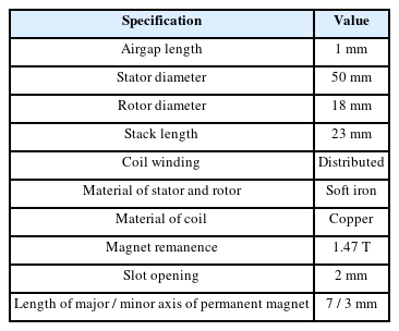
Parameters of the electromagnetic model
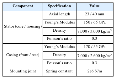
Parameters of the structural model
The proposed model calculated the structural response by combining the electromagnetic and structural models, utilizing input current and rotor position measured during the experiment, as detailed in Section 3. The structural vibration data were obtained from the surface of a PMSM structural model, specifically from a point resembling the actual measurement point illustrated in Fig. 2(c), positioned at the midpoint of the PMSM structure in the radial direction.
The vibration data comparison was conducted in the frequency domain to extract critical information regarding the PMSM’s health status from individual frequency components. Fast Fourier Transform (FFT) was employed using MATLAB to process both experimental and model-predicted vibration data. The data were sampled at an identical rate of 25,600 Hz over a duration of 0.1 second, ensuring uniform frequency resolution. The frequency range was limited to 1,000 Hz to focus on key frequency components while operating the PMSM at a rotating frequency of 20 Hz. Furthermore, the vibration amplitude was normalized by the amplitude of a main electromagnetic force frequency. This normalization facilitated the observation of varying vibration responses under different operating statuses.
Fig. 3(a) illustrates the resultant comparison of vibration responses between the experiment and model. Both exhibit a clear electromagnetic and structural response combination. The 8-pole PMSM is expected to display electromagnetic force frequency at 8 times its rotating frequency, including harmonic components, which in this case, due to operation at 1,200 RPM, would manifest at 160 Hz and its multiples [28]. Both experimental and model data distinctly showcase these components at 160 and 320 Hz. The vibration amplitudes were normalized by the amplitude of 320 Hz component, which is the main electromagnetic force component.
Vibration comparison between the experiment and model prediction under different operational conditions, (a) PMSM without an external rotor, (b) PMSM with an external rotor, and (c) PMSM with a severely unbalanced rotor
Further analysis revealed the dominance of structural response in the higher frequency domain, attributed to exciting the natural frequency of the PMSM system. The structural parameters shown in Table 2 were adjusted values to replicate similar structural response at this frequency region. Both experimental and model data demonstrated similar structural responses in this frequency range, indicating the model’s capability to replicate the vibration response of the PMSM when the external rotor is not connected. The proposed model, despite excluding the rotor effect, adequately replicated the response where vibration of mechanical sources was not distinctly observed in this experiment.
Fig. 4 displays the experimental waterfall graph utilized to confirm the vibration components across various frequencies. The test involved gradually increasing the speed up to 5,000 RPM to distinctly identify the vibration sources. Speed proportional sources, observed at 8 times the rotating frequency and its harmonics, are predominantly visible in the graph, indicating their association with electromagnetic forces. Additionally, there exists a consistent vibration frequency across all speeds, likely attributable to the natural frequencies of the system. Notably, one such natural frequency is observed below 1,000 RPM. Consequently, the vibration sources illustrated in the comparison at the representative speed of 1,200 RPM could be confidently validated through this experimental data.
Waterfall graph of the experimental vibration of a rotor disconnected PMSM
4.2 Vibration Response of a PMSM with an Unbalanced Rotor
This section compares the vibration responses of a rotor connected PMSM. The model utilized the response derived from the rotor dynamic model, integrated with the structural model. Correspondingly, the experiment involved connecting the external rotor to the PMSM through a coupling mechanism. Additionally, a separate experiment was conducted to induce severe unbalance conditions by introducing additional mass into the disk attached to the external rotor.
First, the experimental vibration measurement without severe unbalance conditions was showcased, focusing on the measurement point located at the bearing housing as depicted in Fig. 5. This measurement point isolated the vibration effect solely from the rotor, highlighting vibrations caused by the rotor’s impact. Two noticeable components emerged distinctly at 20 Hz and 260 Hz, corresponding to the rotating frequency and the rotor’s natural frequency, respectively. Parameters of the rotor dynamic model were adjusted to match the observed natural frequency in this experiment, as detailed in Table 3. Subsequently, the structural response was obtained, integrating the computed response from the proposed rotor dynamic model, mirroring the approach from the previous section.
Vibration measurement at a bearing housing point
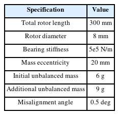
Parameters of the rotor dynamic model
Fig. 3(b) demonstrates a comparison of vibrations within the PMSM structure when the rotor is connected. The experimental vibration data distinctly manifest primary frequency components, showcasing contributions from electromagnetic, rotor dynamic, and structural responses. Specifically, the electromagnetic components at 160 and 320 Hz, along with the structural natural frequency in higher frequency range, align precisely with the observations made in the previous section, when the external rotor is not connected. Moreover, vibration frequencies at 20 Hz and 260 Hz correspond to the rotor response illustrated in Fig. 5. The overall response represents the cumulative effect of the rotor dynamic response integrated into the original PMSM response, mirroring a similar outcome from the proposed model.
It is important to note that although the experiment didn’t deliberately introduce unbalanced mass, a vibration peak at the rotating frequency was observed due to inevitable mass unbalance stemming from manufacturing errors in the testbed. Consequently, the model should consider this factor by incorporating an initial unbalanced mass parameter into the rotor dynamic model. Additionally, misalignment effects need consideration in this model, since the rotor’s natural frequency might not be excited solely by the input force of the unbalanced mass, given their rotating frequency of only 20 Hz. However, electromagnetic effects could potentially stimulate its natural frequency as they encompass higher frequency components.
The limitation of this model becomes apparent in the observed differences in amplitude at the structural natural frequency. These differences may stem from factors not considered in this study, intentionally simplified for efficient data generation. Specifically, the model overlooked the varying displacement of the PMSM’s internal rotor in the electromagnetic model and omitted additional forces arising from rotor misalignment in the rotor dynamic model. The PMSM’s rotor displacement, changing with the orbit of the external rotor, can influence the electromagnetic field within the PMSM in practical scenarios. Furthermore, moment force was exclusively applied to the rotor dynamic model to represent misalignment, neglecting the potential presence of other force components that might coexist. Interactions among these forces can generate higher harmonic force components, potentially exciting increased vibration amplitudes in the structural response, especially in higher frequency ranges. Notably, these higher-frequency components could serve as crucial indicators of anomalies, however, incorporating these considerations could significantly burden computational time. Therefore, the simplified method proposed in this study effectively replicates varying significant vibration frequency components, albeit at the expense of neglecting these factors, which were deemed negligible for the primary focus on rotor fault diagnosis.
The subsequent comparison involved the introduction of additional mass into the rotating disk, altering the unbalance parameter, which was also considered in the model. The resulting comparison, as depicted in Fig. 3(c), revealed an increased vibration peak at the rotating frequency of 20 Hz, whereas other components such as electromagnetic force and the natural frequencies of both the PMSM and rotor remained consistent with the previous comparison. The model accurately mirrored this intensified vibration peak by incorporating a higher amount of unbalanced mass parameters. Consequently, this series of comparisons provided valuable insight into which vibration frequencies warrant focus for rotor fault diagnosis in PMSM vibration data.
In summary, the proposed model was proficient in generating vibration data when the rotor was connected to the PMSM, effectively replicating unbalanced conditions. Notably, the model adeptly combined electromagnetic, structural, and rotor dynamic characteristics present in the actual PMSM vibration measurements. This integration can significantly aid in modeling rotating systems and constructing a digital twin model of such systems for predictive maintenance and fault diagnosis purposes.
5 Conclusion
This study introduces a comprehensive model aimed at replicating the genuine vibration response of a PMSM featuring an unbalanced rotor for generating fault data. The multiphysical model, integrating electromagnetic, rotor dynamic, and structural aspects, was crucial in accurately predicting the unbalanced response within the PMSM structure. Experimental validation confirmed the effectiveness of the proposed model in faithfully replicating all characteristics observed in electric motor connected to unbalanced rotor. Specifically, the initial findings highlighted the successful prediction of combined electromagnetic and structural responses when the rotor remains disconnected from the motor. Subsequently, the model accurately replicates the rotor dynamic response when the rotor is connected to the motor, showcasing its capability even under severe unbalanced scenarios. This proposed model, capable of generating high-fidelity fault data related to rotor unbalance, holds substantial promise in enhancing existing fault diagnostic methods for electric motors. It excels in replicating dynamic responses occurring during faults in external rotors, providing a valuable tool for fault detection and diagnosis. However, the proposed method exhibits limitation that pave the way for future research. Particularly, the current model did not explicitly consider the changes in electromagnetic fields corresponding to the rotor’s orbit variations for a more intuitive and effective vibration data generation. Moreover, the proposed model assumed a certain degree of inherent misalignment in the rotating system and did not consider the resultant translational forces from this condition. Addressing these aspects could significantly enhance the model’s robustness and accuracy in generating fault data for a broader spectrum of faulty conditions in electric motors. Therefore, future works will focus on expanding the model’s scope to encompass other potential faults within rotating systems. Specifically, model will be developed to account for varying degrees of misalignment. Adopting an iterative multiphsyics modeling approach among separate models also holds promise for substantial advancements in constructing a high-fidelity model. Consequently, leveraging virtually generated data within a high-fidelity finite element model will pave the way for constructing digital twin models. Generated data from these models will facilitate constructing digital twin model for real-time prediction of system faults, thereby significantly contributing to the advancement of predictive maintenance strategies and enhancing overall system reliability.
Notes
Funding
This research was supported by the National Research Foundation of Korea (NRF) funded by the Korean Government (MSIT) (No. 2020R1C1C1003829) and by the Korea Institute of Machinery and Materials as part of the project ‘Development of core technologies for digital transformation to enhance the total life-cycle safety of next-generation special vessels’.
Conflict of interest
The authors declare that they have no known competing financial interests or personal relationships that could have appeared to influence the work reported in this paper.
List of Symbols
B
Magnetic Flux Density
μ
Permeability
L
Stack Length
T
Torque
m
Unbalance Mass
α
Misalignment Angle
e
Mass Eccentricity
w
Rotor’s Rotational Speed
ρ0
Mass Density
C
Strain Tensor
u
Displacement
σ
First Piola-Kirchhoff Stress
References
Biography

Hyunseung Lee is M.S. candidate in the Department of Mechanical Convergence Engineering, Hanyang University. His research interest is multiphysics modeling of electric motors.

Seho Son is Ph.D. candidate in the Department of Mechanical Convergence Engineering, Hanyang University. His research interest is data-driven prognosis and health management and deep neural network for remaining useful life estimation.

Dayeon Jeong is Ph.D. candidate in the Department of Mechanical Convergence Engineering, Hanyang University. His research interest is multiphysics modeling of electric motors.

Kyung Ho Sun is Principal Researcher in the Department of System Dynamics, Korea Institute of Machinery & Materials. Dr. Sun’s research interests include prognostics and health management for rotating machinery.

Byeong Chan Jeon is Senior Researcher in the Department of System Dynamics, Korea Institute of Machinery & Materials. Dr. Jeon’s research interests include prognostics and health management for rotating machinery.

Ki-Yong Oh is Associate Professor in the School of Mechanical Engineering, Hanyang University. Dr. Oh’s teaching and research interests include applied dynamics and prognostics and health management in the field of complex energy systems.