
 E-mail
 Print
Print facebook
 twitter
 Linkedin
 google+
1 Introduction
Phase-modulated interferometry has become an important technique to assess the surface and optical thickness of optical devices used in high-precision instruments in the past few decades [1,2]. By changing the phase difference between two reflected beams, three or more fringe patterns are acquired by several methods [3]. We can determine the phase distribution of the acquired patterns using a phase-modulated algorithm.
Phase modulation can occur by moving a reference mirror pushed by a piezoelectric transducer (PZT). In this case, linear miscalibration and nonlinearity of the phase modulation commonly cause systematic errors in the determined phase [1]. In addition, the phase modulation can occur by varying the wavelength of a laser diode through the variation of the injection current [4]. In phase-modulated interferometry using a laser diode, a change in laser power related to the variations of the current causes the intensity modulation of the fringe pattern that can degrade the accuracy of the interferometric assessment [5,6].
Several authors have proposed phase-modulated algorithms to suppress the error sources [7ŌĆō19]. Schwider and Hariharan proposed 5-fringe algorithm [7,8] that can suppress the linear miscalibration of the phase modulation, but not nonlinearity and intensity modulation. Larkin and Oreb derived a symmetric (N+1)-fringe algorithm [9] using a Fourier representation [20]. However, this algorithm does not suppress the intensity modulation. Surrel developed a complex polynomial theory to derive the windowed phase-modulated algorithm [12] that can suppress the linear miscalibration of phase modulation and compounding error. However, SurrelŌĆÖs algorithm cannot suppress the nonlinear intensity modulation.
To compensate for the bias modulation of the intensity, Onodera proposed a 6-fringe algorithm [13] based on the least-square fitting method [21]. However, it is difficult to assess the surface of highly reflective, transparent samples using OnoderaŌĆÖs algorithm since this algorithm does not suppress the second harmonics. In case of the surface assessment of the highly reflective sample, the harmonics should be suppressed [22]. In addition, the nonlinearity of intensity modulation should be considered when applying the wavelength-modulating diode laser to actual interferometric measurements. However, there is no report regarding a phase-modulated algorithm that can suppress the nonlinear intensity modulation.
In this paper, 19-fringe phase-modulated algorithm is derived for suppressing up to first order nonlinearity of intensity modulation. The properties of the developed algorithm are discussed by visualizing them in the frequency domain through the Fourier representation [20]. It is indicated that the phase error of the 19-fringe algorithm is the smallest compared to those of conventional phase-modulated algorithms. Finally, the surface assessment of the transparent fused silica plate is performed by combining a wavelength-modulating Fizeau interferometer with 19-fringe phase-modulated algorithm.
2 19-fringe Phase-modulated Algorithm
2.1 Complex Polynomial of Phase-modulated Algorithm
During the wavelength modulating, the signal irradiance of the fringe pattern in a laser Fizeau interferometer is defined by [22,23]
where Am, jm, and gm are the amplitude, phase, and fringe contrast of the mth harmonics and ar is a phase-modulated parameter. We can calculate the target phase jm using the phase-modulated algorithm.
When using equal intervals of d = 2p/N rad to separate the reference phases, where N is an integer, an M-fringe phase-modulated algorithm is defined by [3]
where I(ar) is the rth irradiance signal defined by Eq. (1) and ar and br are the rth sampling components. The design of a phase-modulated algorithm refers to the determination of sampling components ar, br, and sampling number M.
When nonlinearity occurs during wavelength modulating, the real phase-modulated value ar is a polynomial function of the ideal phase-modulated value a0r, including the phase-modulation error e:
where a0r = 2p[r ŌłÆ (M + 1)/2]/N, e0 is linear miscalibration of the phase modulation, eq (1 Ōēż q Ōēż p) is the qth nonlinearity of phase modulation, and p is the maximum order of the nonlinearity.
For designing an error-compensating phase-modulated algorithm, many authors have proposed several systematic approaches based on the averaging method [7,11], a linear equation [10,15], and complex polynomial theory [12,14, 18,19]. Surrel developed the complex polynomial P(x) of a phase-modulated algorithm [12], defined in the following Eq. (4), to determine the phase-modulated algorithm.
where x = exp(imd) and i is the imaginary unit.
In SurrelŌĆÖs theory [12], the insensitivity of the phase-modulated algorithm to the higher harmonics and phase-modulation errors is determined by the properties of the polynomial roots in the complex diagram. For instance, the phase-modulated algorithm that has single roots on the complex diagram can suppress the mth harmonics [3,12]. In addition, the phase-modulated algorithm that has a double root at m = ŌłÆ1 is insensitive to linear miscalibration of the phase modulation e0 [9,12].
2.2 Derivation of 19-fringe Phase-modulated Algorithm
To compensate for linear modulation of intensity, Onodera developed a 6-fringe algorithm [13] based on the least-square fitting method [21]. Surrel described this insensitivity to the intensity modulation using complex polynomial theory [14], where
From Eq. (5), insensitivity to the linear intensity modulation during wavelength modulating can be satisfied when the complex polynomial of a phase-modulated algorithm has a double root at m = 0. To compensate for the first order nonlinearity of intensity modulation, a triple root should be located at m = 0 on the complex diagram of the phase-modulated algorithm. Surrel also derived a 5-fringe algorithm that has similar characteristics to those of OnoderaŌĆÖs 6-fringe algorithm [14]. However, complex polynomials of these two algorithms do not have a root at m = 2, which means that these two algorithms are vulnerable to the second harmonics [14]. For this reason, the highly reflective surface of the silicon wafers or transparent parallel plates cannot be assessed by OnoderaŌĆÖs 6-fringe and SurrelŌĆÖs 5-fringe algorithms [22,24].
In this study, SurrelŌĆÖs complex polynomial theory is used to derive new phase-modulated algorithms. The roots of the complex polynomial are determined considering the following requirements:
Compensation for:
i. The mth harmonics of the signal irradiance.
ii. The linear miscalibration and nonlinearity of the phase modulation.
iii. The compounding errors between the higher harmonics and linear miscalibration of phase modulation.
iv. The first order nonlinearity of the intensity modulation while modulating the wavelength.
Satisfaction of the fringe contrast maximum condition.
To assess both surface and optical thickness of a transparent sample, we assign eight to the phase division number N (N = 8) [16].
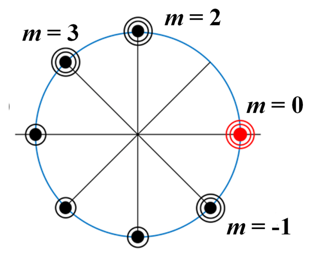
Fig. 1 represents the root location and multiplicity of the complex polynomial of the 19-fringe algorithm. First, the complex diagrams of the algorithm should contain the single roots, except at m = 1 (x = exp(id)), to compensate for the mth harmonics [3,12]. In addition, the complex diagrams of the algorithm should contain the double roots, except at m = 1, to compensate for the linear miscalibration of phase modulation and compounding errors between the higher harmonics and linear miscalibration [12,25]. The complex diagram of the algorithm should have a triple root at m = ŌłÆ1 to compensate for the first order nonlinear phase modulation [25]. Furthermore, the complex diagram of the algorithm should contain a triple root located at m = 0 to compensate for the first order nonlinearity of the intensity modulation [25]. Finally, by locating the triple root at m = 2 and 3 on the complex diagram, the fringe contrast maximum condition can be satisfied [18]. To derive the 19-fringe phase-modulated algorithm, we expand the complex polynomial shown in Fig. 1.
Based on Fig. 1, the complex polynomial P(x) of 19-fringe algorithm is given by
where z = exp(ip/4). The sampling components ar and br of the 19-fringe algorithm can be calculated by expanding Eq. (6) and separating the real and imaginary numbers and given to
2.3 Fourier Representations of Phase-modulated Algorithms
We can visualize the phase-modulated algorithms by using Fourier representation [9,20]. To visualize the algorithms in the frequency domain, we define the sampling functions for the sampling components of the phase-modulated algorithm expressed in Eqs. (9) and (10).
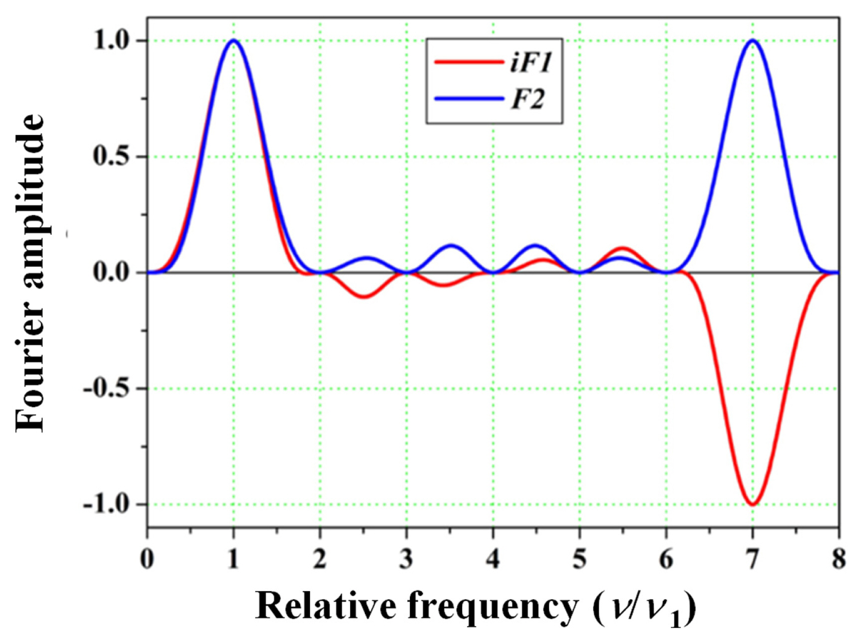
where n is the frequency variable. F1 and F2 are purely imaginary and real functions based on the symmetric properties of the sampling components ar and br [10,15]. Fig. 2 represents the iF1 and F2 of the 19-fringe phase-modulated algorithms.
The configuration of the sampling functions iF1 and F2 represent the error-compensating ability of the phase-modulated algorithm [9,10,14,15,18,25]. Since the sampling functions of the developed algorithm shown in Fig. 2 have zero gradients at the n/n1 = 1, this algorithm can suppress the linear miscalibration of phase modulation and satisfy the fringe contrast maximum condition [9,18]. In addition, Fig. 2 shows that the second order derivatives of the sampling functions are zero at the n/n1 = 1, which indicates that 19-fringe algorithm is insensitive to the first order nonlinear phase modulation. The sampling functions of the algorithm shown above have zero gradients n/n1 = 2, 3, ŌĆ”, NŌĆō2, which indicates a compensation ability for the compounding errors between the higher harmonics and linear miscalibration of phase modulation [15,25].
Finally, the sampling functions should have zero gradients at n/n1 = 0 to compensate for the linear modulation of intensity [14]. The sampling functions shown in Fig. 2 have zero gradients at n/n1 = 0. In addition, the second order derivatives of the sampling functions shown in Fig. 2 are zero at the n/n1 = 0, which indicates that 19-fringe algorithm possesses a compensation ability for the first order nonlinearity of intensity modulation.
3 Error Analysis
Due to the nonlinear intensity during wavelength modulating, the intensity amplitude Am of the mth harmonics can be expressed as
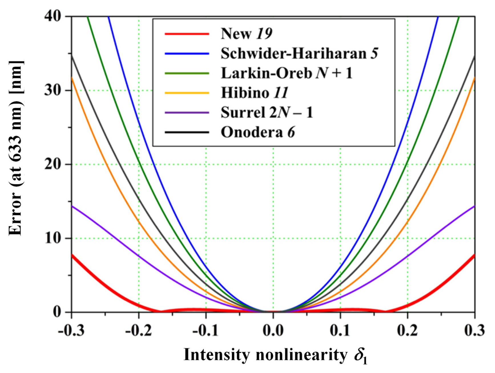
where d0 is the coefficient of intensity modulation and dp (p 1) is the pth nonlinearity coefficient of intensity modulation. Fig. 3 shows the calculated phase error for nonlinearity of intensity defined by Eq. (11) based on the phase-modulated algorithms listed in Table 1. The phase errors shown in Fig. 3 indicate that the difference between the calculated phase without intensity modulation and the calculated phase containing nonlinear intensity using Eqs. (2) and (11).
From Fig. 3, the new 19-fringe algorithm shows the smallest calculated phase error among those of the conventional phase-modulated algorithms listed in Table 1. Particularly, by suppressing the nonlinearity of intensity d1 to a value less than 0.1, the 19-fringe algorithm achieves precise measurement with sub-nanometer accuracy. The phase errors by the Schwider-Hariharan 5-fringe [7,8] and Larkin-Oreb N+1 [9] algorithms are the largest since these algorithms do not possess the compensation ability for intensity modulation. HibinoŌĆÖs 11-fringe, SurrelŌĆÖs 2NŌĆō1, and OnoderaŌĆÖs 6-fringe algorithms can compensate for the linear modulation of intensity, but cannot compensate for the nonlinearity of intensity modulation. Therefore, these three algorithms show larger errors than that of 19-fringe algorithm.
4 Experiment
4.1 Wavelength-modulating Fizeau Interferometer
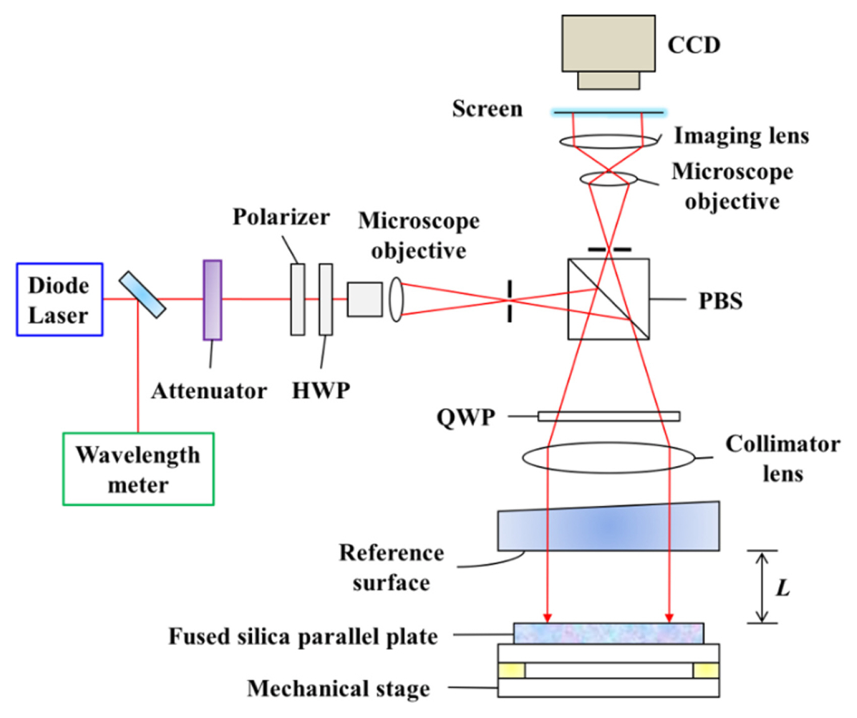
By combining a wavelength-modulating Fizeau interferometer with the new19-fringe phase-modulated algorithm, we assess the surface of an 80-mm-diameter, 8-mm-thick fused silica plate. The fused silica plate is placed horizontally on a mechanical stage with an air-gap distance of L = 2 mm. Fig. 4 depicts the experimental setup for surface assessment of the fused silica plate using the wavelength-modulating Fizeau interferometer.
We maintain the laboratory temperature at 20.5┬░C, and use a tunable diode laser source with a Littman external cavity (New Focus TLBŌĆō6300ŌĆōLN). During the surface assessment, we linearly modulate the wavelength of the diode laser source from 632.8 nm to 638.4 nm by using a picomotor and PZT [26]. The beam from the diode laser source is split by a beam splitter. Two divided beams are directed to a wavelength meter (Anritsu MF9630A) and the Fizeau interferometer. The accuracy of the wavelength meter is calibrated with 10ŌłÆ7 at a wavelength of 632.8 nm. The beam incident to the interferometer illuminate the surfaces of the reference and parallel plate through the collimator lens and the reflected beams from these surfaces generate the fringe pattern. We acquire the interferogram using the CCD camera with a resolution of 640 ├Ś 480 pixels.
4.2 Results and Discussion
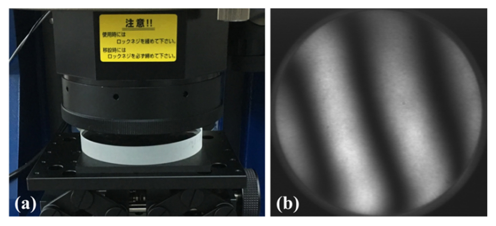
Fig. 5 depicts a photo of the transparent fused silica plate in the wavelength-modulating Fizeau interferometer and a raw interferogram of the sample at a wavelength of 632.8 nm. We calculated the necessary range of wavelength modulating dl as follows:
We finely modulate the wavelength from 632.8198 nm to 633.1189 nm, and acquire 19 interferograms at regular wavelength intervals in 10 s. Due to the nonlinearity of the diffraction grating in the laser source, the nonlinear response of ~3% occur in the PZT. For linearly modulating the wavelength of the laser source, we incrementally apply a quadratic voltage to the PZT so that the nonlinearity decrease to 1% of the total phase modulation.
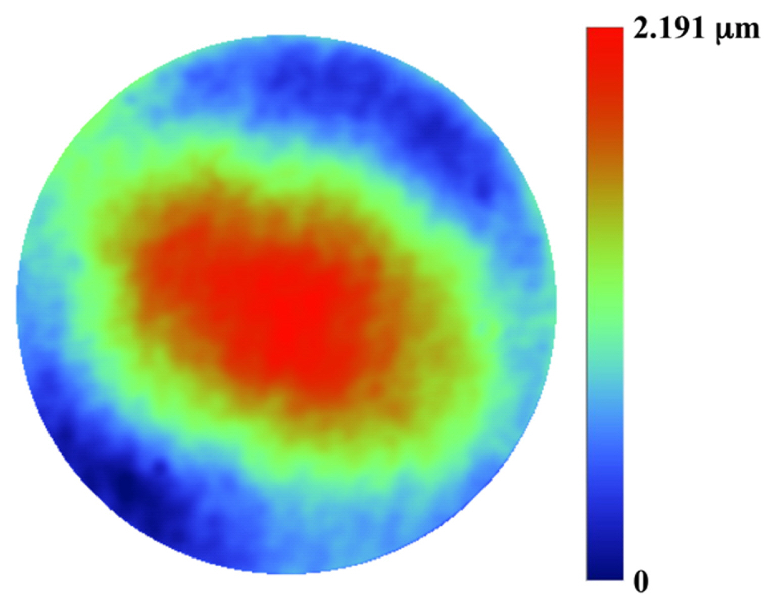
We assess the surface of the fused silica plate using the acquired interferograms and proposed 19-fringe phase-modulated algorithm, as depicted in Fig. 6. The assessed surface has a concave configuration with an amplitude of ~2.2 mm.
The repeatability error of the surface assessment is 4.042 nm. The uncertainty of the reference surface and the wavelength meter are l/20 and 10ŌłÆ7, respectively, resulting in an overall measurement accuracy of 34 nm.
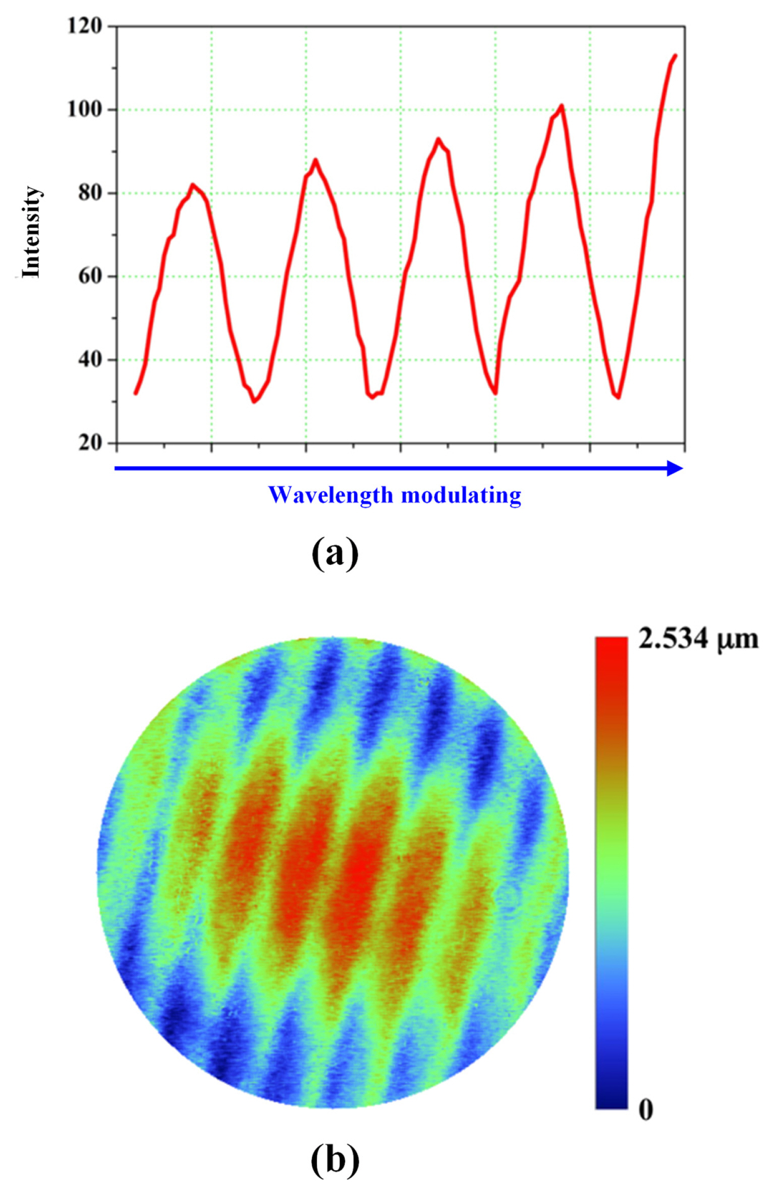
Next, the wavelength is modulated with intensity modulation, as shown in Fig. 7(a). We assess the surface of the transparent plate using the phase-modulated algorithms listed in Table 1. The surfaces of transparent plate assessed by theses algorithms other than 19-fringe algorithm contain significant ripples due to the sensitivity to the nonlinearity of intensity modulation. As a representative of these results, Fig. 7(b) shows the surface of the transparent plate assessed by the Larkin-Oreb N+1 algorithm [9]. In Fig. 7(b), considerable ripples can be observed because this algorithm does not possess the compensation ability for the intensity modulation. For intensity modulation, as shown in Fig. 7(a), the surface determined by the 19-fringe algorithm shows the same configuration with no ripples observed. Due to the substantial ripples, the repeatability error of the surface assessment by the LarkinŌĆōOreb algorithm is ~885 nm.
5 Conclusion
We propose the derivation process for 19-fringe phase-modulated algorithm that can suppress up to first order nonlinear intensity modulation. For discussion of the properties of the phase-modulated algorithm, the developed algorithm is visualized over the frequency domain using the Fourier representation. In addition, the compensation ability for the intensity modulation is demonstrated using the phase error when nonlinearity exists during wavelength modulating. The surface assessment of the transparent fused silica plate is performed using the 19-fringe algorithm and a wavelengthmodulating Fizeau interferometer. The repeatability error of surface assessment by the 19-fringe algorithm is ~4 nm. The whole measurement uncertainty is 34 nm including the accuracy of the reference surface, l/20~30 nm.
Even with the nonlinearity of intensity, the results calculated by the 19-fringe algorithm show almost the same configuration as for the case with no intensity nonlinearity. In contrast, the surface shapes determined using other algorithms show considerable ripples for the nonlinearity of intensity modulation.
Hence, the proposed phase-modulated algorithms are expected to enhance the managing process of the optical devices because these algorithms can suppress up to first order nonlinearity of intensity modulation when assessing the surface and optical thickness of the transparent plates. Moreover, based on SurrelŌĆÖs complex polynomial theory, the proposed phase-modulated algorithm can be extended to suppress the higher order nonlinearity of intensity modulation.


 PDF Links
 PubReader
 Full text via DOI
 Download Citation
  CrossRef TDM


