

 E-mail
 Print
Print facebook
 twitter
 Linkedin
 google+
1 Introduction
Additive Manufacturing (AM) processes fabricate parts by adding and processing material in a layer-by-layer manner. This manufacturing approach has important implications on part characteristics, manufacturing practices, and design opportunities, among other topics. DFAM consists of design methods, practices, and tools that encourage designers to explore new design concepts and develop new designs by exploring benefits enabled by the unique capabilities of AM processes. As expressed in reference [1], The main objective of DFAM is to maximize product performance through synthesis of shapes, sizes, hierarchical structures, and material compositions, subject to capabilities of AM processes.” To achieve these benefits, redesigning a component, module, or entire product is necessary; the benefits of using AM for conventional designs are very limited.
Interest in DFAM has increased significantly in recent years, with a series of review articles published that attempt to comprehensively discuss the topic [2–5]. A key idea in DFAM is the distinction between opportunistic and restrictive DFAM, where restrictive DFAM is akin to conventional design for manufacturing, concerned with design details and ensuring manufacturing constraints are satisfied. Opportunistic DFAM is aligned with the quote in the previous paragraph about the DFAM objective, seeking to achieve large benefits from AM.
In contrast to general review papers, this paper identifies four topics that are considered at the frontier of DFAM research and presents them in some detail. They are among the most important topics among those that are relevant to artifacts with significant mechanical engineering content, including design using as-manufactured properties, design for the AM process chain, developing new product architectures, and design for 4D printing. The first of these topics applies to restrictive DFAM while the others are more consistent with the objectives of opportunistic DFAM. Each will be described with research issues highlighted and illustrated with examples. Many other topics on construction, tissue engineering, micro-scale devices, etc. will be out-of-scope for this paper.
2 Design with As-manufactured Properties
As is well known, AM fabricated parts often exhibit anisotropic mechanical properties, particularly in the vertical vs. horizontal directions (with respect to the build direction). Further, properties can vary throughout the part in more complicated patterns. Particularly in metal parts, mechanical properties can be very different in subsurface regions compared to bulk regions. Porosity can follow similar patterns in that near-surface regions of metal parts can have higher porosity than bulk regions. These porosity patterns can significantly affect mechanical properties and fatigue life, among other considerations.
Similarly, polymer parts fabricated by material extrusion (MEX) processes also exhibit porosity patterns and other directional characteristics that lead to significant anisotropy.
Shape distortions can arise due to several process-related effects, such as residual stresses that build up from the layer-by-layer build process. These distortions can affect the entire part. Other distortions are more localized and arise due to process resolution, scan pattern, and material behavior effects. In MEX, sharp corners are difficult to achieve due to the limited resolution of deposited beads. In material jetting processes, corners and other shape transitions are rounded, in part, due to the tendency of liquid droplets to flow before solidification.
From a design perspective, designers must be able to include as-manufactured properties and characteristics such as these during design. The designer must be able to determine the extent to which specifications can be met. Without accurate analyses, part and system performance cannot be determined, which can lead to poor design decisions.
Several research issues are apparent. First, shape distortions and property distributions must be determined. Second, they need to be represented so they can be incorporated into analysis models. Many as-manufactured properties and characteristics can be determined through high fidelity simulations of the manufacturing process. Particularly with powder bed fusion (PBF) and directed energy deposition (DED) processes, good process simulation software is available both commercially and from research institutions [6]. Although simulation is a good solution, simulations can require significant computational resources taking many hours to run. As such, long simulation times reduce the number of design iterations that can be performed. Furthermore, design optimization requiring many iterations becomes infeasible.
An alternative to high fidelity simulations is surrogate models that are fast to analyze but have limited resolution or accuracy. For design exploration or optimization, their limited accuracy can be acceptable as has been demonstrated in voxel-based designs on single [7] and functionally graded materials [8]. A promising surrogate modeling approach is based on machine learning methods trained on simulation results. In our previous work, we developed a 3D convolutional neural network (CNN) model of residual stresses and distortions as a function of part geometry [9]. PBF process simulations of approximately 800 geometric models containing simple shapes (thin walls, struts) and their combinations were performed to train the 3D CNN. Tests on more complex models demonstrated the capability of predicting distortion and stress trends accurately.
Certainly, other types of surrogate models could be developed that may perform at least as well. The important point is that accurate methods of predicting as-manufactured properties for arbitrary part geometries are needed but are challenging to develop.
The second issue on property distribution representation is simpler conceptually, but raises modeling and computational issues for its solution (see e.g. [10,11]). The objective of the representation is to enable fast construction of performance analysis models. Since the properties needed for analysis models depend on the material and its processing, what is needed is a model of the material’s process-structure-property (P-S-P) relationships. This topic is the focus of the Integrated Computational Materials Engineering (ICME) domain, which has received enormous attention in recent years [12]. Research in ICME is inherently multi-scale, starting with molecular dynamics or CALPHAD (CALculation of PHAse Diagrams) simulations for nano-scale properties [13,14]. Results become inputs for higher level models that compute micro-scale properties, ending with continuum models that can be used for macro-scale simulations. For design, the P-S-P relationships need to be inverted so that material composition, microstructures, and manufacturing process variables can be determined given desired macro-scale properties. The relationships are often represented using surrogate models, such as Gaussian process regression or neural networks. Inversion may be performed numerically or directly in the case of some neural networks [15–17].
Other computational issues arise directly with analysis models. For example, our research utilized voxel part models for PBF process simulation so that simulation results were associated directly with voxels. Finite element analysis (FEA) models with voxel elements were easily constructed to perform structural analyses. Somewhat more generally, if the FEA model uses the same mesh as the process simulation, then FEA is greatly simplified. However, if different meshes are used, then some type of interpolation will be required to determine properties that are appropriate for the analysis and mesh.
Many topics for future research are evident in this area.
3 Design for the AM Process Chain
3.1 Motivation
Rather than focus design efforts on only the AM process, it is important to design for the entire manufacturing process chain that includes all post-processing operations. Virtually all AM processes require post-processing so consideration of the entire process chain during design is critical for any process to achieve design requirements. For metal parts, heat treatment, support structure removal, and finish machining are frequently required to convert the AM-fabricated part to its final state. Also, polymer parts usually require some post-processing operations, including support removal and finishing [1]. A technique called the Process Chain Map (PCM) is introduced in this paper that explicitly relates design requirements for the part to each step in the AM process chain. This PCM visually shows the role of each step in the process chain and facilitates communication among design and manufacturing personnel.
A framework for part design across the process chain is presented based on the PCM. The objective of the framework is to ensure that part designs are optimized for performance and for the capabilities and limitations of each manufacturing process. Accordingly, each step in the process chain should be optimized for the system-level objectives, in addition to part performance optimization. Leveraging multidisciplinary design optimization (MDO) methodology, the framework includes design optimization problem formulation where the system level design problem is decomposed into a series of subsystem problems that correspond to the steps in the process chain. Requirements embodied in the PCM are incorporated into the design problem formulation. Influences of manufacturing processes on each other throughout the process chain are modeled using coupling variables among the corresponding subsystems. A metal PBF part example illustrates how these ideas fit together.
3.2 Process Chain Map
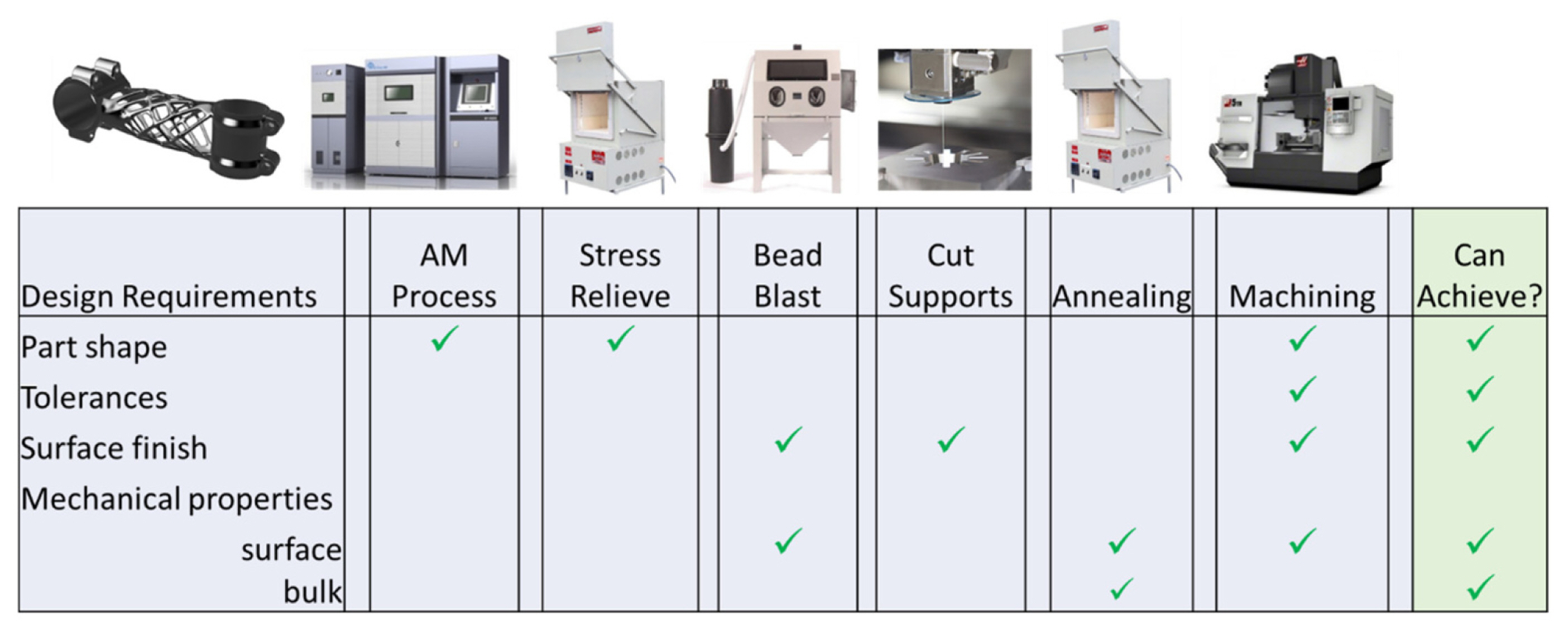
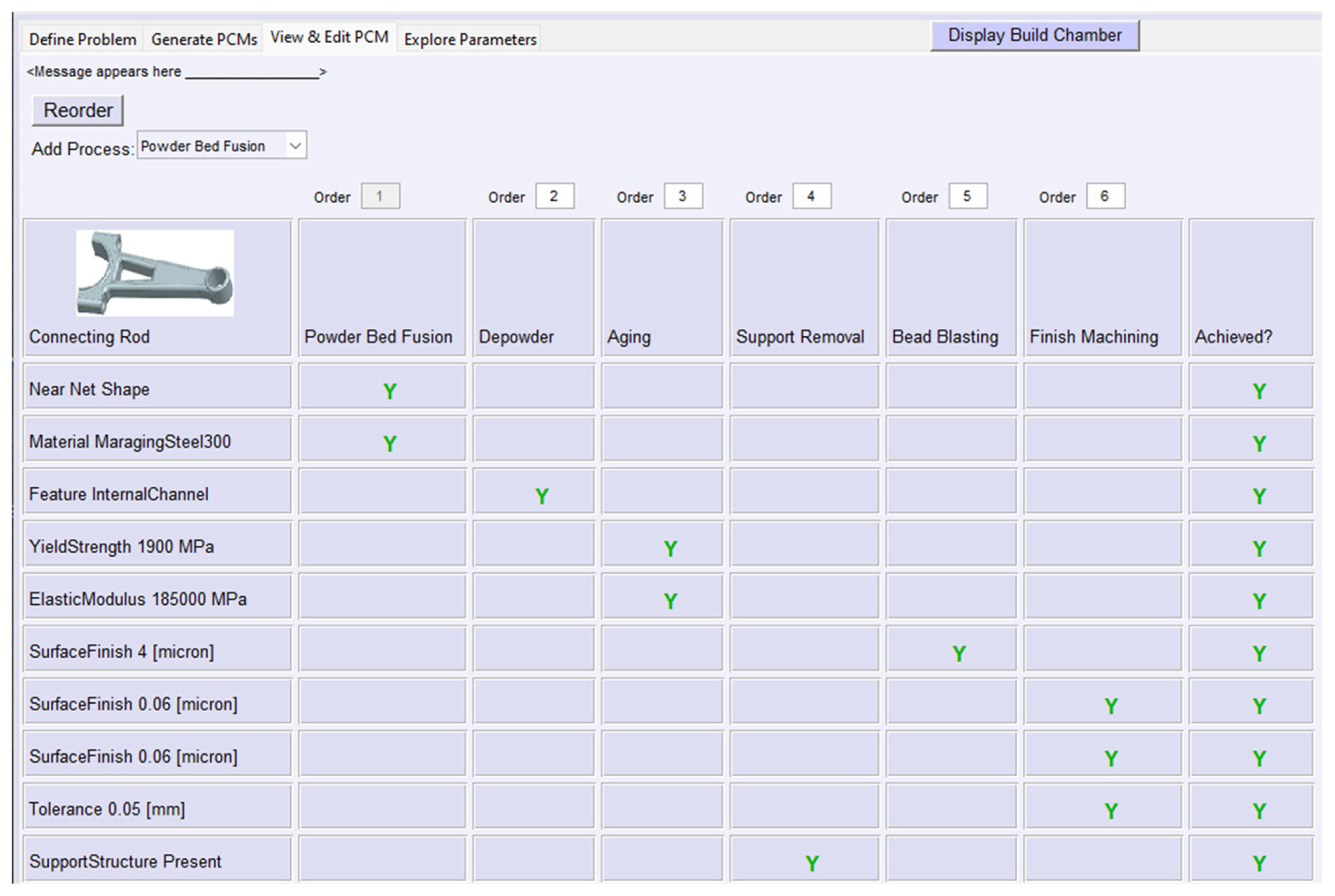
The process chain map (PCM) is intended to be a visual representation of the relationships between steps in the process chain and how those steps contribute to satisfying design requirements [18]. An example PCM for metal PBF is shown in Fig. 1. Across the top is the sequence of manufacturing processes in the process chain. The first column contains the design requirements for the part in terms of shape, tolerance and surface finish requirements, and mechanical properties. The user of the PCM needs to decide the level of detail of the requirements. For a specific part design, it may be important to include different tolerances if they are achieved by different manufacturing processes. In this example, different mechanical properties are included for bulk regions of the part, as well as surface properties, but this may not be relevant to all parts. In the body of the PCM, entries (green checks) indicate which processes contribute to achieving the requirement.
In this illustration, the process-requirements relationships are shown qualitatively. An alternative usage of the PCM is to include quantitative values in the table to indicate the extent to which the requirement is achieved or the specific values of, for example, mechanical properties are achieved by the process. This is similar to the development of Quality Function Deployment charts [19] that capture qualitative relationships between customer requirements and engineering characteristics.
The PCM can serve multiple purposes. First, it documents the process chain for the part so that all participants in product development can understand the sequence of processes. The PCM aids communication among the product development team. Also, the PCM clarifies the role of each process in the process chain, indicating to which requirement(s) it helps satisfy. Further, software implementations of the PCM can be used for various design, manufacturing, and management purposes including team communication, production planning and scheduling, supply chain configuration, and process planning, among others.
3.3 Additive Manufacturing Process Chains
As illustrated in Fig. 1, AM process chains can be extensive. Final part characteristics can be rather different than those produced by the AM process and it is imperative that designers design with final part properties and characteristics.
In metal PBF, parts are fabricated with support structures, also called anchors, that fix the part to the build platform and prevent the part from warping due to residual stresses. Support structures also conduct heat from the laser to the build platform to reduce the likelihood of hot spots. These supports need to be removed by a machining operation: cutting, EDM, machining, etc. However, if supports are removed while the part has significant residual stresses, it can deform considerably. To prevent this, a stress relief heat treatment is typically performed while the part is still attached to the build platform. The stress relief not only relaxes residual stresses but can also modify and homogenize metal microstructures and significantly reduce mechanical property anisotropies. Additionally, annealing, solution annealing, and aging heat treatments may also be performed to modify microstructures and properties, in addition to (or instead of) stress relief.
After PBF, parts are buried in the powder bed, so the loose powder must be removed. Sometimes, technicians use brushes to remove powder particles from part surfaces, crevices, or holes. Automated depowdering stations are also available to automatically rotate build platforms with parts to facilitate powder removal from different directions and internal channels. Part surfaces tend to be fairly rough after metal PBF so various surface finishing operations may be performed on parts before or after removal from the build platform. Blasting with beads, sand, and ice is common. Finish machining is also common for part surfaces that have high accuracy, shape, or surface finish requirements.
Most of this discussion applies to metal directed energy deposition (DED) processes as well, except that parts are not buried in a powder bed. Parts are typically built on a build platform; parts either need to be removed from the platform, or the platform is incorporated into the part design, but often needs to be cut to shape. Heat treatments and finish machining are common.
For polymer processes, the process chain is also important. Support structures are used in most polymer processes, except for PBF. Surface treatments (bead blasting, sanding) are commonly used to provide desired surface finish. Some machining or hand work may be performed to ensure correct shapes and accuracy requirements are met.
3.4 Design for the Process Chain Method
A framework has been developed for the design of parts for the process chain, based on methods from MDO [20,21]. The objective is to design part shapes and find dimension values that satisfy as well as possible design requirements and constraints. Many times, these requirements and constraints will not be satisfied by the AM process, which is why subsequent post-processing steps are needed.
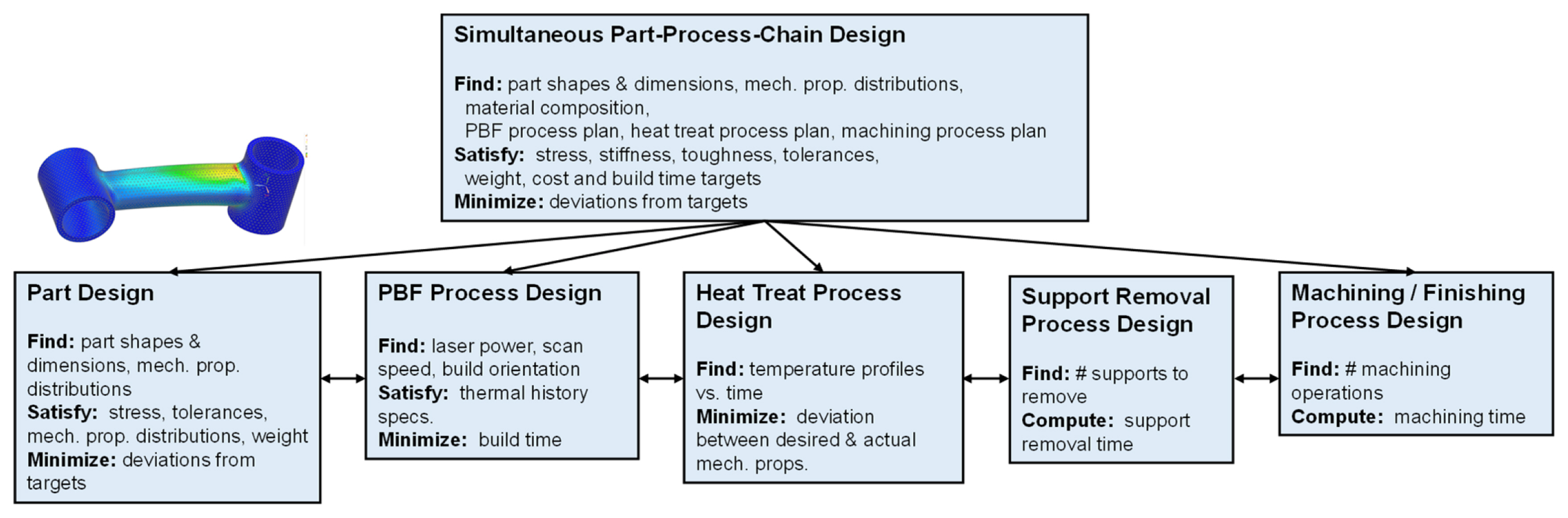
The proposed approach starts with the formulation of the overall design problem, that is referred to as the part-process chain co-design problem. An example problem formulation is shown in Fig. 2 (based on [22]). At the top, the overall problem formulation is given as finding part shapes and dimensions, part characteristics, and process settings for all the manufacturing processes in the process chain. This MDO problem seeks to minimize a measure of deviation from goals on, for example, performance requirements (e.g., maximum stress, maximum deflection), economic objectives (build time, cost), and weight. Design variables, constraints, and objectives should be derived from the requirements and manufacturing operations in the PCM.
The overall problem is decomposed into various subsystems that represent each step of the process chain, as well as part performance design. An advantage of this approach is that typically different analyses are performed for the different subsystems and these analyses can be performed independently from one another. The disadvantage is that the various subsystem design problems cannot be solved independently. This is easy to see if we consider mechanical properties. Elastic modulus and yield strength, among other properties, are needed for structural performance analysis of the part being designed. If fatigue is important, then surface roughness is important to consider. Since these properties and characteristics are the results of the entire process chain, the subsystem design problems are coupled, which has important implications. First, problem coupling means that some design or intermediate variables are shared between multiple subsystems. Mechanical properties, such as elastic modulus, are good examples of coupled quantities. Second, the problem structure usually determines the sequence that subsystem problems should be solved. With few exceptions, the subsystem solution sequence should be the same as the process chain, with part design being the last subsystem to be solved.
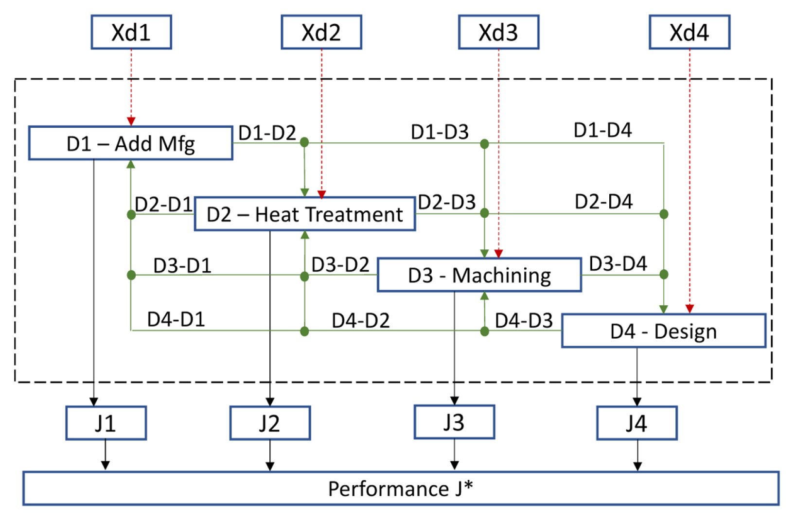
To deal with subsystem coupling and identify suitable workflows, we use an extended design structure matrix diagram [23], as shown in Fig. 3. In the middle part of the figure, the four boxes denote four subsystems from Fig. 2, but note that part design corresponds to the box labelled ‘D4 – Design’ and support removal is not shown for simplicity. D1–D3 are the three manufacturing processes in the process chain. Information flows are indicated by the green solid arrows that connect the boxes. Output variables from D1 flow to D2, D3, and D4. Similarly, output variables from D2 flow to D3 and D4, etc. Additionally, outputs from D2–D4 can flow back up to D1 and potentially the other boxes (the diagram is shown fully connected but need not be so). Solid black arrows pointing downwards from the D1–D4 boxes indicate optimization objectives, J1 to J4 respectively, that are computed by the subsystems. These objective quantities are inputs to the system-level performance evaluation where they are used to compute overall optimization objective function J*. Execution proceeds sequentially from D1 to D4 then to the system level performance evaluation. After evaluation, the system level optimization tests for convergence; if not converged, iterations continue starting again at D1.
With this presentation, it should be clear that the process chain map can be used to directly develop part design optimization problems for the process chain that can be solved using MDO methods.
3.5 Connecting Rod Example
3.5.1 Problem Description
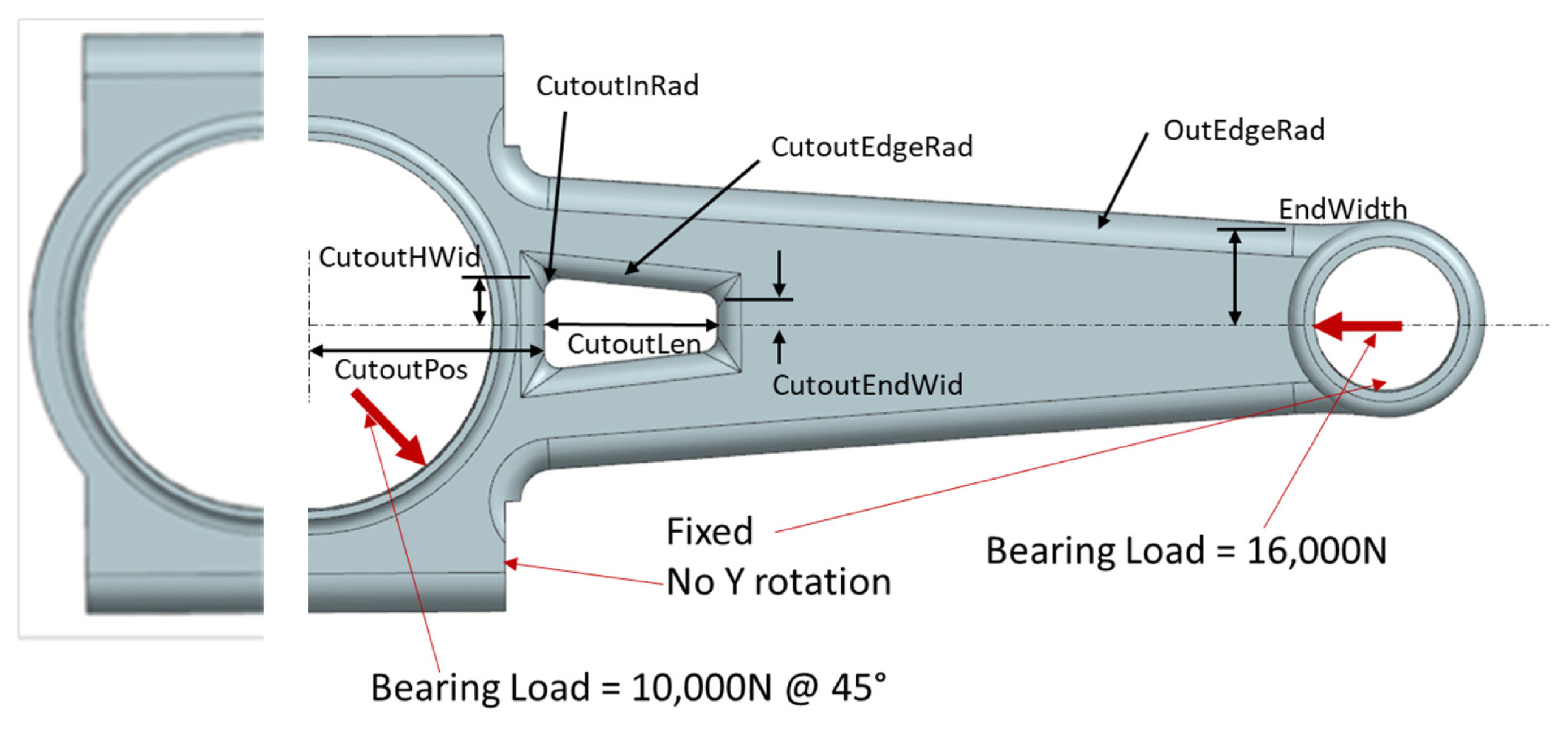
An automotive connecting rod will be used to illustrate the application of the design for the process chain method, as shown in Fig. 4. Connecting rods connect pistons in the engine to the crankshaft to drive the vehicle. The specific connecting rod design is from a Ferrari 308 V8 engine that was in production from 1975–1985. The right half, which will be designed, has overall dimensions of 143x73x20 mm and a mass of 0.4518 kg. Grade 300 maraging steel was the material selected and production manufacturing is planned using the PBF process.
Requirements for the connecting rod include supporting expected loads, light weight, cylindricity tolerances on the cylindrical bores at its ends that mate with the crankshaft and piston, a dimensional tolerance on the bore centerline distance (136.9±0.05 mm), and surface finish requirements overall (< 4 mm Ra) and in the bores (< 0.06 mm Ra). Loading conditions are shown in Fig. 4, with an axial compressive load of 16,000N on the piston bore and a 10,000N load at 45° from axial on the crankshaft bore. These loads were derived from Ref. [24] at the point of maximum bending.
The type of design problem in this example is called design exploration, where the purpose is to identify regions of the design space that contain promising designs worthy of continued engineering. This contrasts with standard optimization where an optimal design is sought. In design exploration with multiple objectives, the common approach is to develop solutions for different weights (importances) on the different objectives. In this example, shape optimization will be used to reduce part weight and manufacturing time, while increasing stiffness based on eight size variables that control part shape, which are shown in Fig. 4. The length and ends of the connecting rod are fixed, as is height at 20 mm. Most of the variable dimensions are associated with the cutout. Additionally, one dimension controls the width of the right end (EndWidth) and another controls the edge round radius along the outside of the part (OutEdgeRad).
3.5.2 Process Chain
The AM process chain consists of the PBF process followed by heat treatment, support structure removal, bead blasting, and machining, as shown in the PCM in Fig. 5. For maraging steel, aging heat treatments can affect mechanical properties greatly. Support structures will be removed using EDM. Parts will be bead blasted to ensure that surface finishes overall are below 4mm Ra. Finally, finish machining will be performed on the bores to ensure that tolerances and surface finish requirements are met. From a design perspective, the AM process, heat treatment, support structure removal, and finish machining processes will be included in the problem formulation. The first two processes affect mechanical properties, while part orientation changes the number of surfaces that need support structure and, hence, the support structure removal time. As can be seen in the right-most column of the PCM, all requirements can be achieved using this process chain.
3.5.3 Problem Formulation
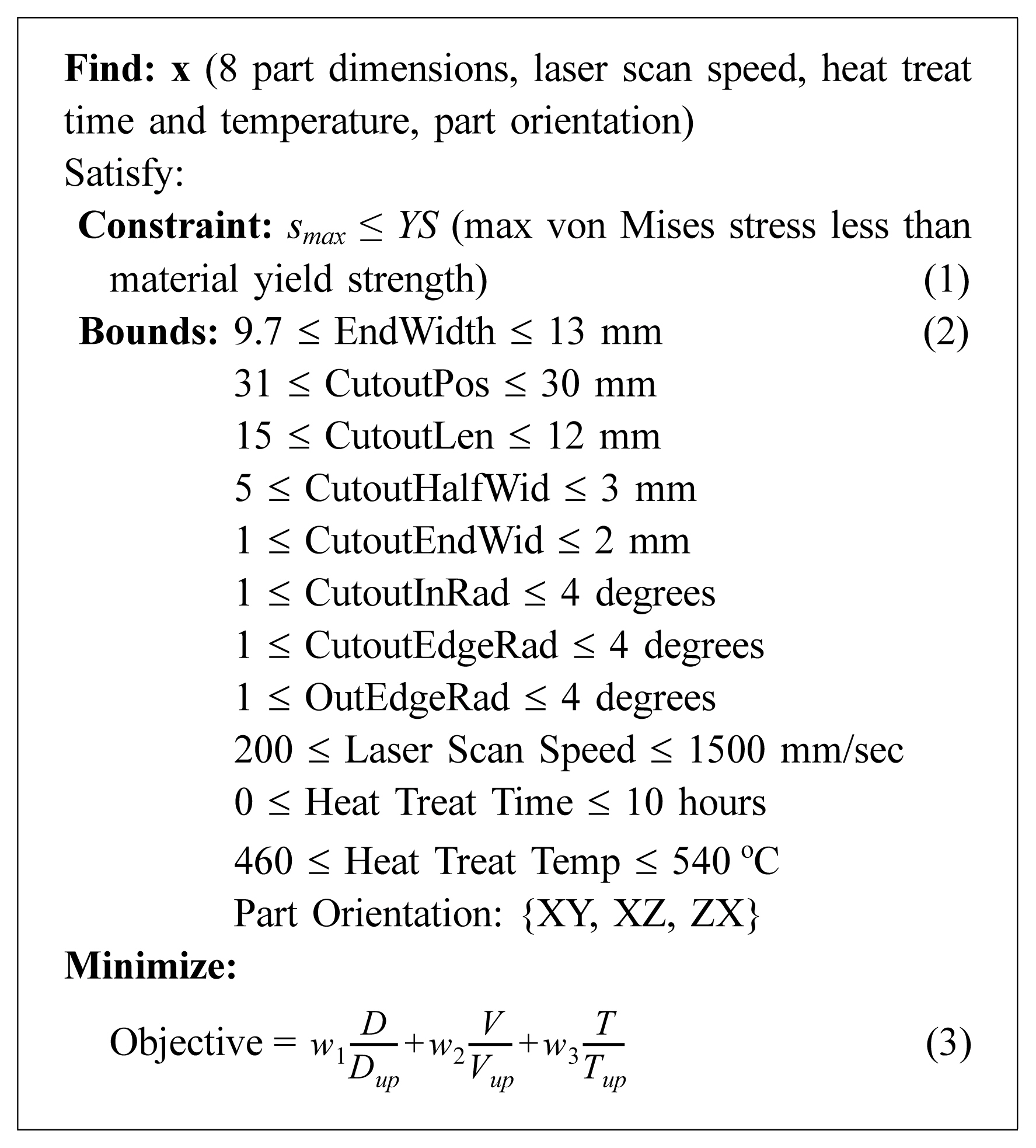
The problem formulation to be used in this example is a simplified version of the problem shown in Fig. 2. This formulation was used for multiobjective optimization at each sampled point from the performance space. For the connecting rod, the objectives include minimum deflection, volume (weight), and manufacturing time, subject to a yield stress constraint. Eight part dimensions will be the part design variables, as mentioned. Additionally, laser scan speed, heat treatment time and temperature, and part orientation in the PBF process will be the process design variables. Note these process variables affect both mechanical properties and fabrication time. This formulation is shown in Fig. 6. Lower and upper bounds are given for each design variable, along with their definition. The objective function in Eqn. 3 is a weighted sum of normalized objectives on deflection, D, volume, V, and fabrication time, T. Weights are indicated as wi and should sum to 1. Each objective is normalized by an upper bound (Dup, Vup, Tup) that was chosen to be slightly larger than the maximum computed during optimization.
For part design, several surrogate models were developed to relate design variables to the performance objectives and the yield stress constraint. That is, surrogate models related the 8 dimensions and elastic modulus to maximum deflection, volume, and maximum yield stress. FEA was used to compute deflections and stresses for different combinations of variables.
A simplified PBF process model was developed that estimated laser scan time as a function of the part dimensions. Since scan time is the only variable component of PBF fabrication time, that is sufficient for this example. Elastic modulus and yield strength were modeled as weak functions of laser scan speed using experimental data from the literature [25–27].
For the heat treatment process, the temperature and duration of treatment were design variables. An extensive literature survey was performed on PBF fabricated maraging steel to collect data on mechanical properties as a function of heat treatments [28]. These data were used to develop response surface models of yield strength and elastic modulus as a function of heat treatment temperature and time.
The amount of support structure depends on the part orientation. For the XY orientation, only one surface of the connecting rod needs supports, the front surface seen in Fig. 4. Support structure removal time was estimated at 0.25 hours per part. In contrast, the XZ and ZX orientations require support structures in the bearing surfaces and the cutouts, in addition to the lowest lateral surface in that orientation. Support structure removal time was estimated at 0.75 hours per part for those orientations due to the increased number of supported surfaces.
For design exploration, the performance space defined by the objectives is sampled by varying weights on the objectives. Assuming that objectives are normalized, the weights should be between 0 and 1. For each combination of weight values, multiobjective optimization is performed to find the part design that best meets the objectives with the specified preference structure.
3.5.4 Results
For design exploration, the performance space, defined by objectives on volume, maximum deflection, and build time, was sampled by varying weights on the three objectives between 0 and 1. Matlab function ‘fmincon’ was used for multiobjective optimization. Then, the set of solutions was viewed using several different tools. First, a ternary plot was generated that shows objective function values across the range of weights. Second, a plot of the three objectives in 3D space was generated.
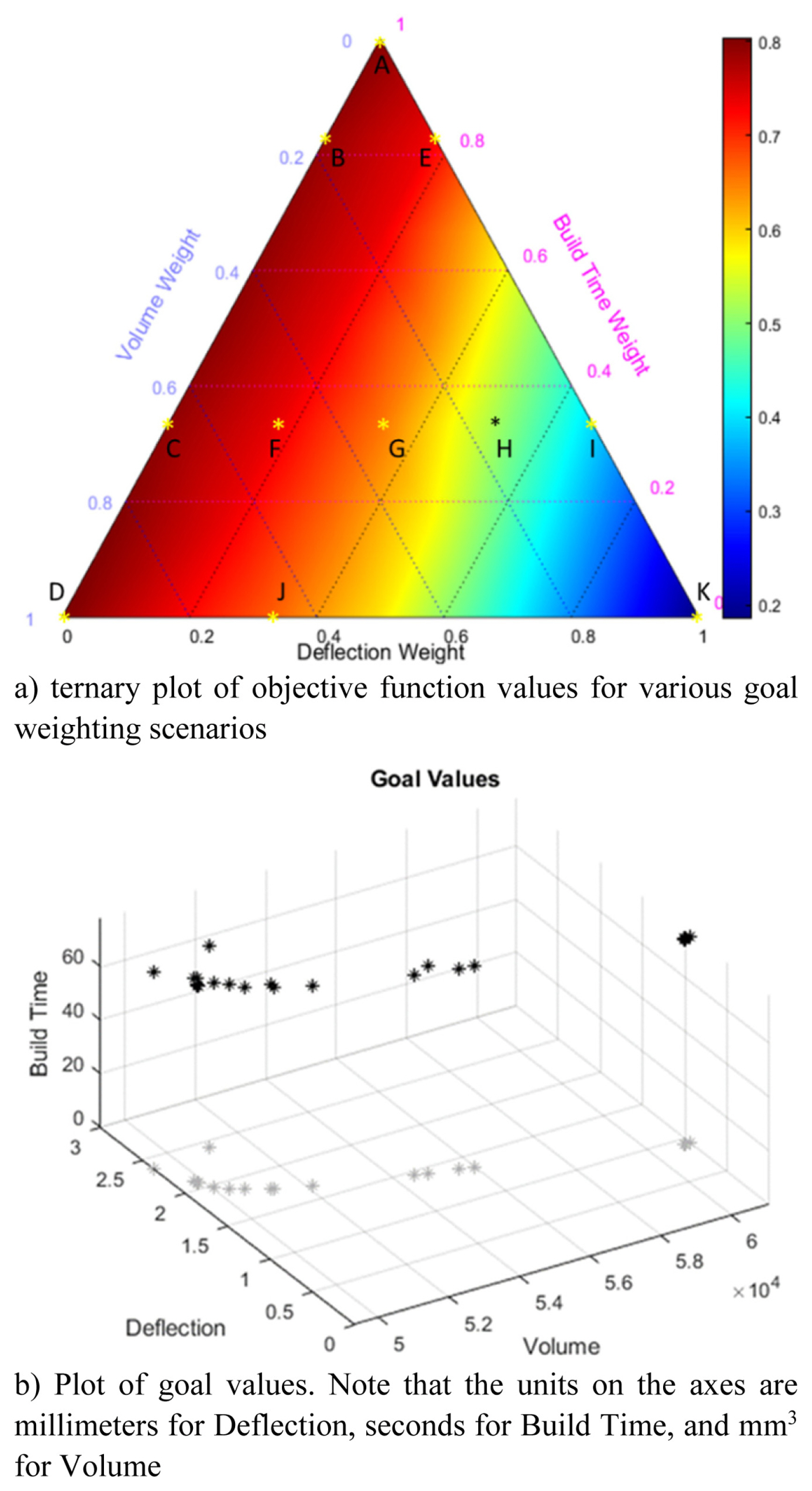
The ternary and objectives plots are shown in Fig. 7 for the case of ZX build orientation, where the connecting rod was vertical. Highlighted in Fig. 7a are 11 solutions, labeled A–K. Note that some process parameters were held constant: bead blasting time was 1.5 hours and finish machining time was 0.5 hours.
For the ternary plot, the three objectives correspond to the three axes. The color map shows overall objective function values (Eqn. 3). The plot clearly shows that the deflection and build time objectives control the overall objective values since the color map changes almost linearly along these axes. The lowest objective values are in the lower right corner where deflection has the highest weight and build time has the lowest.
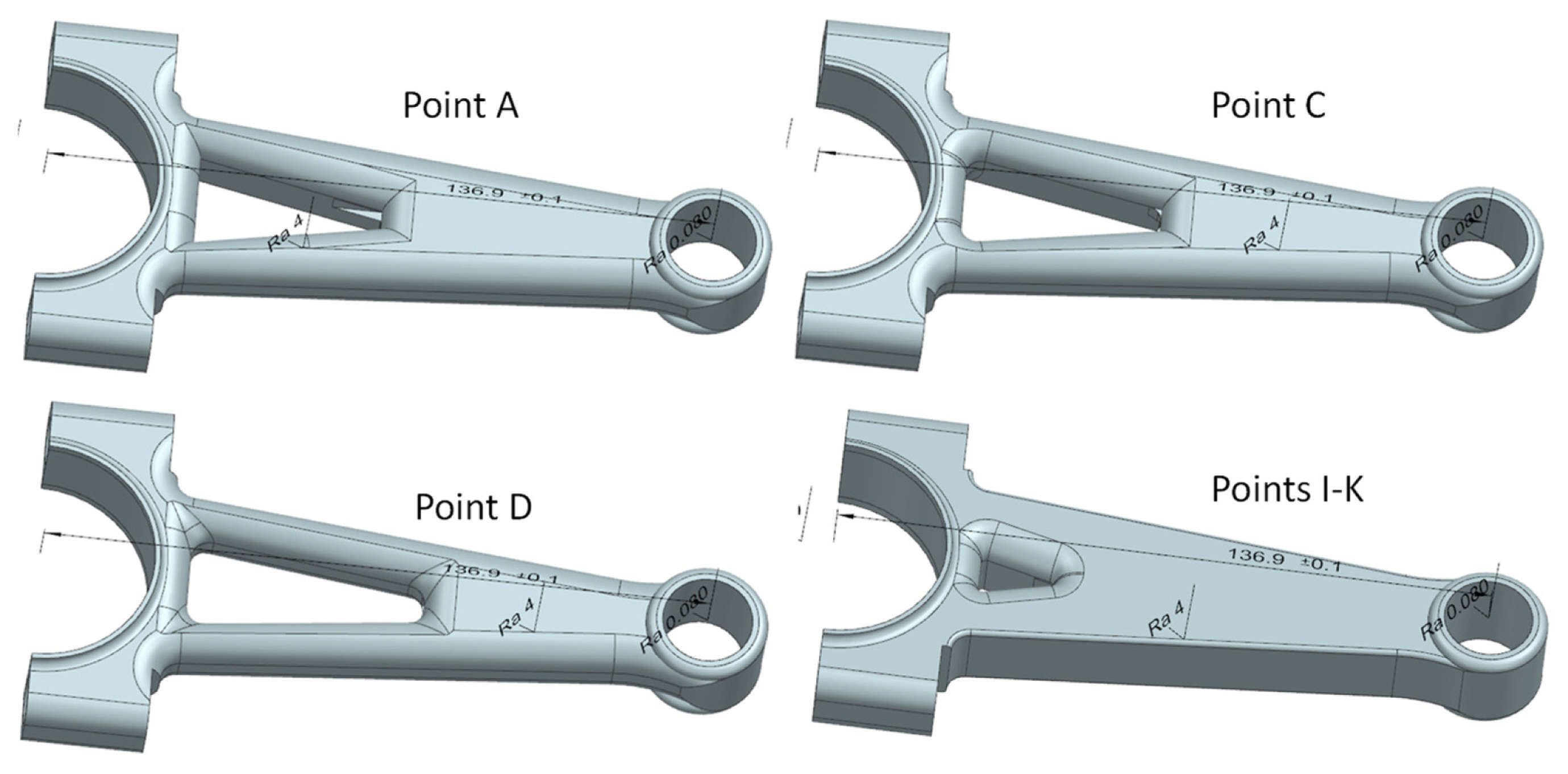
Along the Volume axis, connecting rod designs are fairly similar, with large cutouts and large values of edge round radii. At point A (Build Time weight = 1), the cutout length is 37.91mm and increases to 48.43mm at point D. In between, cutout length increases to 48.41mm at point B but decreases to 40.57mm at point C due to interactions among the Volume and Build Time objectives. Connecting rod designs that correspond to points A, C, D, and I–K are shown in Fig. 8.
In the lower right corner of Fig. 7a where objective function values are lowest, we observe a region of the design space that is relatively flat. Designs corresponding to points I, J, and K appear to be very similar. When the Deflection goal is important, the cutout becomes very small, along with edge round radii, regardless of Volume and Build Time weights. In between the Volume axis and the lower right corner, connecting rod designs vary with the cutout and edge round radii becoming gradually smaller. It is interesting to note the influence of heat treatment parameters. Long heat treatment times, at slightly lower temperatures, are evident along the Volume axis. Away from the Volume axis, heat treatment times reduce to between 3–4 hours, but temperatures increase to reduce build time from the nominal 5–6 hours, while providing good mechanical properties that help reduce deflection. This interaction between heat treatment and PBF laser scan speed would have been difficult to identify without a consideration of the entire process chain and illustrates the value of the PCM and the presented design exploration method.
The Pareto front is well defined as shown in Fig. 7b. One point at a deflection of 2.27mm and volume of 50,900mm3 appears to be off the front. This corresponds to point A. Why it is off the Pareto front is probably due to the surrogate models used for analysis or the optimization process converging to a local minimum. This may explain the nonmonotonic behavior of cutout size observed along the Volume axis.
Specific conclusions from this work are as follows. Design for the AM process chain enables investigation of trade-offs among performance and manufacturing objectives and how these trade-offs affect part shapes and sizes. MDO problem formulations help to understand problem structure in terms of interacting subsystems. However, these formulations do not necessarily dictate the use of solution methods for decomposed systems; the single-level solution method used in this paper was effective and efficient in solving the multiobjective optimization problem from Fig. 6. The proposed design exploration method was effective in identifying a promising region of feasible part designs for subsequent engineering. Future work will investigate more complete process models, particularly for AM processes, with more process variables and more detailed surrogate models. Comparisons of decomposed and single-level problem formulations will be studied as will methods for their solutions.
4 Product Architecture Design
The benefits of AM for part consolidation are well known: many examples have been presented where several – or even dozens – of conventionally produced parts are replaced by one AM part. However, larger benefits may be achieved by more radical changes in product structure than simply part consolidation. This section focuses on the benefits of rethinking product architectures.
4.1 What is Product Architecture?
Product structure can be thought of as a collection of functional elements, which focus on the operations and transformations that contribute to the product’s performance, or as a collection of physical components and modules [29]. The relationship between the functional and physical structures is at the heart of product architecture. Stated differently, the product architecture is “the scheme by which the functional elements of the product are arranged into physical chunks and by which the chunks interact” [29].
4.2 Designing Product Architectures
Ulrich and Eppinger [29] proposed a 4-step process for establishing a product architecture: create a schematic of the product, cluster the elements of the schematic, create a rough geometric layout, and identify fundamental and incidental interactions within the product. The first 3 steps are enough for our purposes in this paper.
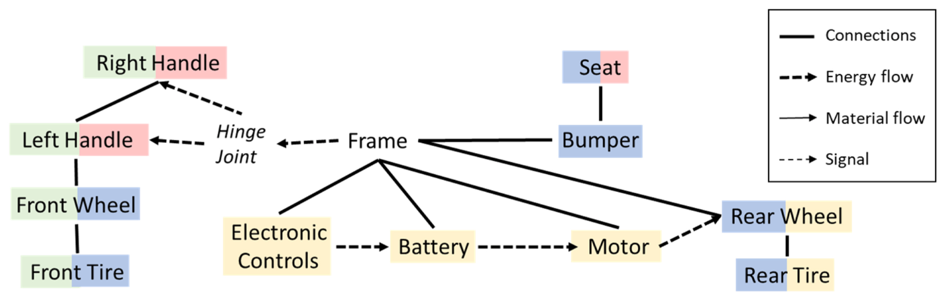
The product schematic is a diagram with the primary functional and physical elements of the product listed, with flows of material, energy, and signals (similar to a function structure) linking the elements. As a result, the schematic describes what the product does (what functions does it perform) and how it performs those functions; that is, which physical elements implement which function(s), what substances flow through these elements, and how everything is controlled.
By investigating integral, versus modular, product architectures, the designer can explore various designs, how they could be fabricated by AM, and the potential benefits that could be achieved [30]. Different physical elements can be explored as well as different function-physical element relationships. Different flows may be possible also.
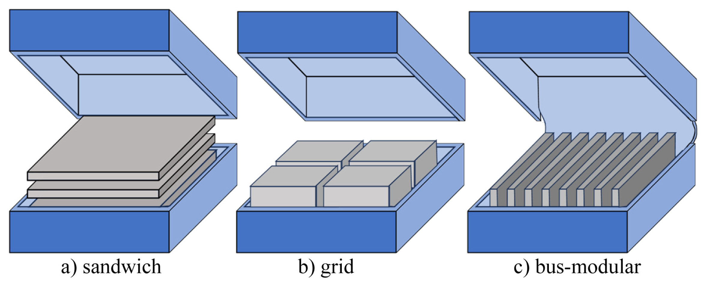
Various geometric layouts of the product are also worth exploring. Assume that a hand-held electro-mechanical product is being designed. Using conventional design approaches and manufacturing processes, the product housing would likely consist of separate top and bottom components so that internal components can be assembled easily. Internal components could be arranged in a bottom-to-top sandwich manner, using a bus-modular structure, or other modular structure. These alternatives are shown schematically in Fig. 9. The sandwich architecture in Fig. 9a may be appropriate if a small number of printed circuit boards (PCB) and other modules can be stacked efficiently; for example, the top gray component may contain user interaction devices that are accessible through the top housing. In contrast, if a greater number of PCBs and other modules are needed, then the bus-modular approach in Fig. 9c may be appropriate. The grid architecture in Fig. 9b may be appropriate if internal components are more block-shaped or irregular in size and do not need to plug into a common bus, as in the bus-modular architecture. Note that the housing in Fig. 9c shows the top and bottom components integrated into a single part connected with a living hinge.
Four levels of product architecture redesign will be considered for this paper:
Function sharing: combine parts that have the same or similar function and that can be of the same material.
Function integration: combine parts that have different functions and that can be of the same material.
Change layout: explore different layouts of existing parts and modules and consider redesigning the parts to achieve function sharing and integration (illustrated in Fig. 9).
Function elimination: simplify product architectures by eliminating a function through a change in module technology and layout.
The first two product architecture redesign levels represent approaches to part consolidation, while the other two represent more significant architectural changes.
4.3 Nera eBike Example
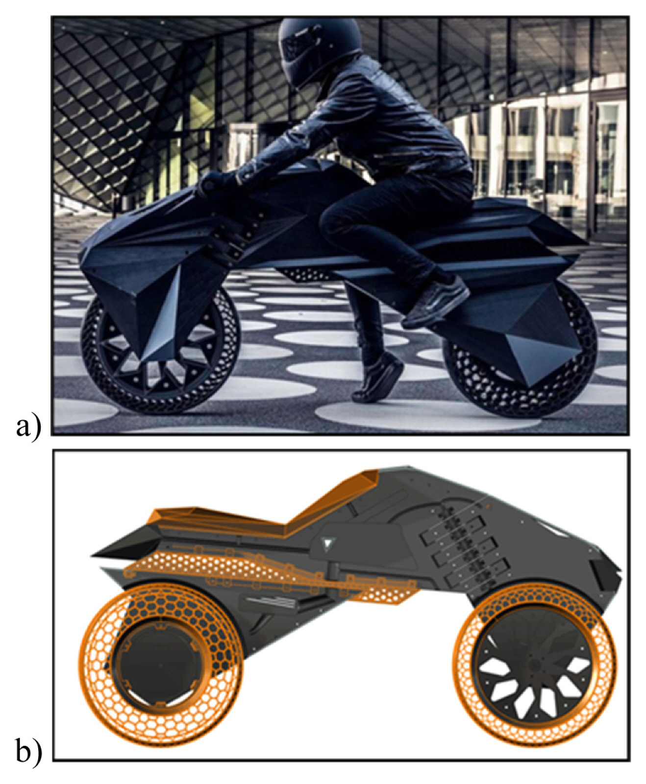
An excellent example of rethinking product architectures is the electric motorcycle example from Nera [31]. This novel design has an architecture that is very different from conventional motorcycles. Shown in Fig. 10, it consists of about 15 plastic parts that were printed using the MEX process. Structural parts were printed using carbon-fiber filled ABS, while flexible components including the tires and seat were printed using an elastomer material as shown in Fig. 10b. Non-AM components included the electric motor, battery, controller, and lights.
As an example of the changing layout architecture design level, the steering function is implemented as left- and right-halves that each includes a handlebar and one side of the steering fork. This contrasts with conventional layouts that consist of a handlebar, steering stem, steering tube, and fork.
An example of function elimination is achieved by replacing the conventional internal combustion engine and transmission with an electric motor and electronic speed controller. In addition to controlling engine and motorcycle speeds, the mechanical transmission also transfers power from the engine to the rear wheel. This power transfer function can be eliminated since the electric motor can be attached directly to the wheel. Note that by replacing the transmission with an electronic controller, many mechanical parts are eliminated, the motorcycle design is simplified, and the eBike can be much lighter.
Other examples of function integration include incorporating suspension system functionality into the wheels and frame of the eBike. Separate suspension components, including springs and shock absorbers, were eliminated. Instead, the honeycomb and cellular designs of the wheel enable some deformation to absorb road disturbances. Similarly, the integral frame flexes somewhat, which helps with the suspension function.
4.4 Exosuit Example
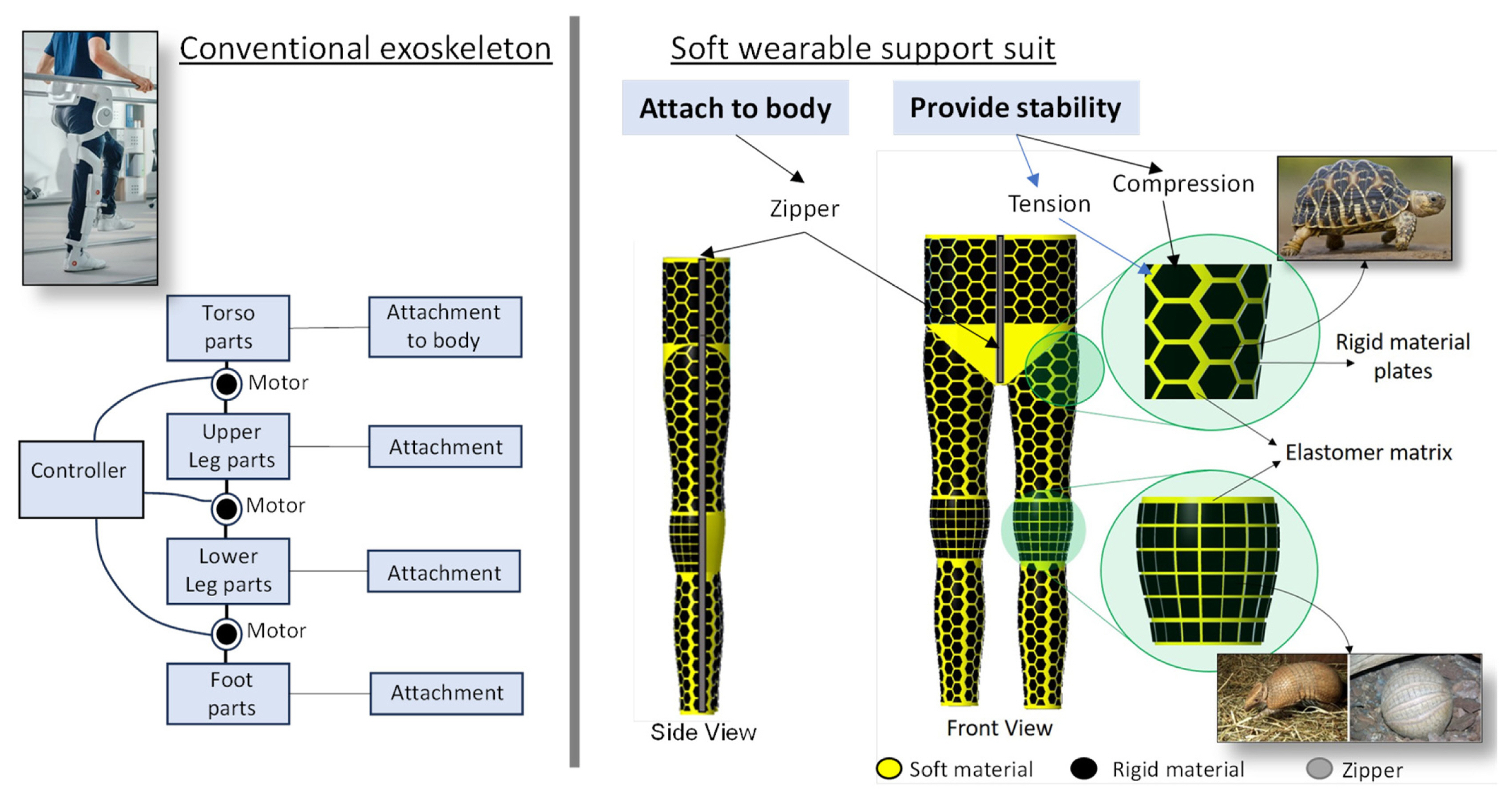
A second example demonstrates the generality of the proposed design approach. Typical exoskeletons are devices worn on the body that assist humans in picking up heavy objects, with applications in construction, manufacturing, the military, and healthcare for moving patients. These exoskeletons are powered and resemble typical robot arms in their construction (see Fig. 12, left). We are interested in developing passive exoskeleton suits (exosuits) that assist people in walking by providing stability and potentially energy storage and release. More specifically, the exosuit should assist walking by preventing instabilities including tipping sideways and tipping forwards or backwards, and is easily wearable (to put on and take off).
An initial solution is shown in Fig. 12 (right) that is a highly integral structure resembling a pair of pants. The exosuit is passive in that no actuators are used, and no power is required. It provides the desired stability, while being easy to wear and take off, with zippers to help attach the suit to the body. The exosuit provides compression on the wearer’s body through the elastomer matrix material and provides stability through a combination of compression and rigid plates laid out to resist undesired motions. The particular structure of the plate layout was inspired by turtle shells and armadillo scales.
This exosuit design can be described as having a highly integral architecture. It differs from conventional exoskeletons since the provide stability function is distributed throughout the suit, in contrast to exoskeletons where stability is enabled by a network of discrete components in a modular manner. Using the terms from Sec. 4.2, the exosuit was redesigned through function integration, function elimination, and changing layouts.
The exosuit design can be fabricated easily using large material extrusion or material jetting processes that are capable of multi-material deposition. Zippers would be separate components that could be integrated during fabrication or assembled afterwards.
Although unconventional, the exosuit example demonstrates that highly integral structures and devices can be designed for AM with product architectures that are radically different than conventional designs.
5 Design for 4D Printing
4D printing is the 3D printing of devices with materials that exhibit shape memory effect [32]. Shape memory polymers (SMP) and shape memory alloys (metals, SMA) are the two most common classes of shape memory materials. When exposed to a specific stimulus, such as heat or humidity, the materials change shape such as stretching, compressing, bending, or twisting. Shape changes induced by exposure to the stimulus typically involve a microstructure change that causes strains. For example, SMAs often switch between martensite and austenite phases that causes strains and shape changes.
Consider the design of a deployable solar panel for a satellite. The panel typically consists of many smaller panels, connected by revolute joints and driven by servo motors, that are folded for launch and deployed after the satellite reaches its orbital location. Such a deployable solar panel consists of many parts and can take a long time to design and assemble. A different design approach is to replace the joints with shape memory hinges, which has the additional advantage of not requiring a motor for each actuated joint. The structure that carries the solar panels could consist of a single part fabricated out of structural material and a shape memory material for the hinges. Although this deployable concept is not yet a reality, it indicates the intriguing potential of 4D printing.
At present, no general methods have been proposed for design for 4D printing, although some review papers [33] and specific methods have been proposed [34,35]. 4D printing and shape memory material literature [36] includes many types of components that exhibit different types of shape changes. If these could be cataloged, a 4D printing design library could be developed that could serve as a knowledge base of “ingredients” for design methods. Other needed developments include a language for describing deployable and morphable device design problems, a method to match problem descriptions to elements in the design library, a method to configure the matched elements into a working deployable or morphable system, and methods for maturing, or fleshing out, the system concepts.
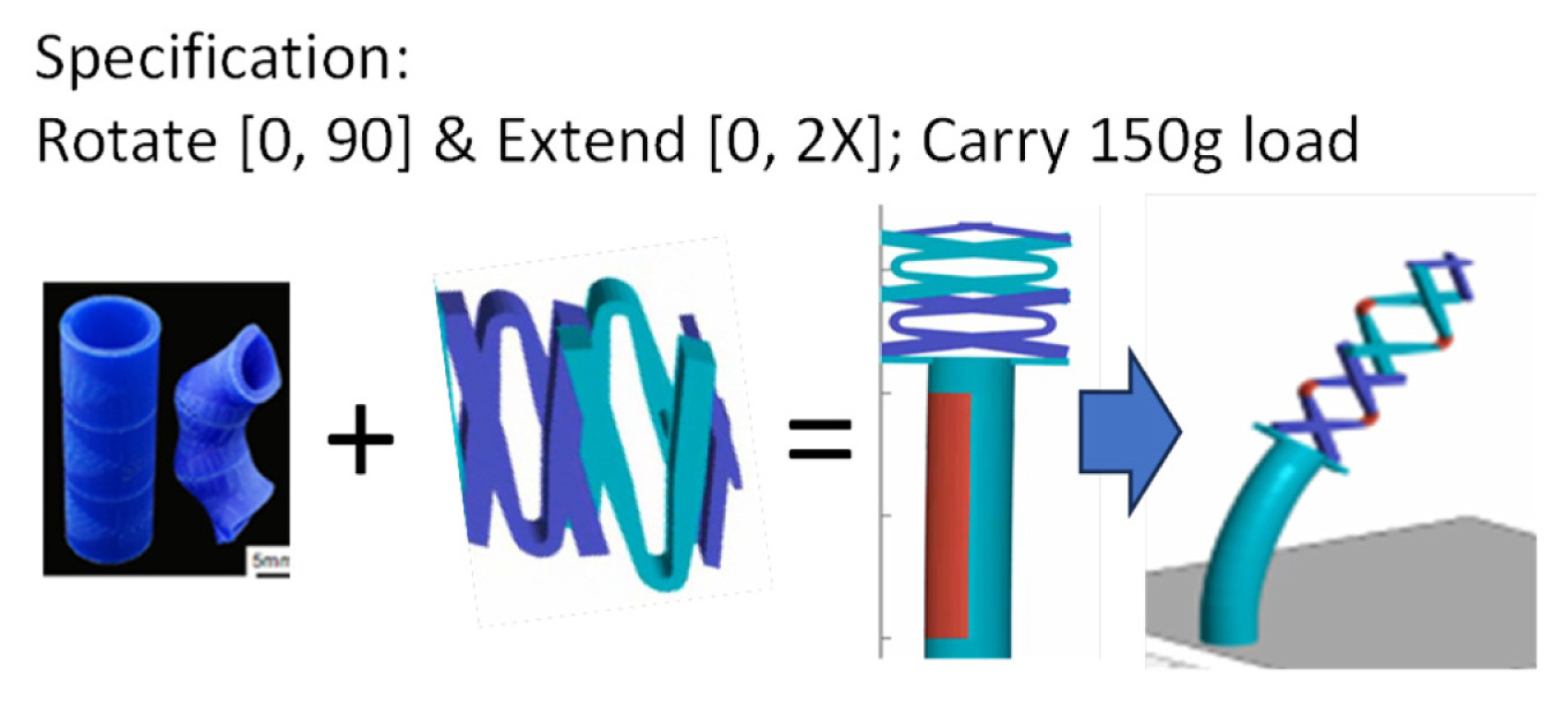
As a simple example, consider the problem of designing a deployable system that bends and extends twice its starting length. This problem specification consists of two different motions, bending and extending. Consider that the first motion specification can be matched to a bending cylinder device, while the second could be matched to a scissor mechanism; we will choose two scissor elements to gain greater extension. To actuate and control system deployment, we can place heaters on the actuator regions and connect them with electrical circuits. In the spirit of 3D printing, we can assume that the heaters and control circuits are fabricated by direct-write MEX processes. The matched components and assembled system are shown in Fig. 13 in their initial and final shapes.
The design example was a simple sketch of one type of design application that can arise. The scope of the design library could be broadened to include origami and Kirigami constructs, compliant mechanisms, and other types of shape changing components. More complicated design problem specifications should be supported. More complicated shape changes should be considered. All these extensions require a much more sophisticated approach to design for 4D printing that should be pursued.
6 Closure
In this paper, the frontier of DFAM research was explored through consideration of four issues. First, methods for including as-manufactured mechanical and other physical properties during computational design were described. Although some broad types of anisotropies are well known, part-specific property distributions often arise, particularly in metal parts. High fidelity simulations were proposed to determine property distributions and approaches to surrogate model development were outlined. These surrogate models can be very useful to enable fast design iterations, either manually by designers or automatically by optimization algorithms.
Second, designing for the AM process chain was explored in detail. Post-processing operations are often needed to achieve final part properties. Since these operations can be extensive and make significant changes to part properties and characteristics, it is paramount that designers design for them. The process chain map was introduced as a visual tool to relate design requirements to steps in the process chain. Then, the PCM could be used to generate a multidisciplinary design optimization problem formulation that enables the designer to explore the design space to find promising regions in that space. An example of an automotive connecting rod was used to illustrate the main methods and results.
Third, by radically rethinking product architectures, perhaps the largest benefit of AM can be achieved. Concepts of product architecture design were introduced and an example of an electric motorcycle was used to illustrate the results. A second example of an assistive exosuit demonstrated the generality of the concepts and approaches.
Finally, 4D printing and the application of the shape memory effect have potential for replacing complex mechatronic systems with simpler, more highly integrated device designs. Some thoughts on design for 4D printing were offered.
Many other research issues are important for DFAM, so of course the issues highlighted in this paper should not be considered the only significant ones. Some review articles on DFAM were referenced for further considerations and guidance on prioritizing topics for research programs.

 PDF Links
 PubReader
 Full text via DOI
 Download Citation
  CrossRef TDM


